Case Study: Closed-Loop Temperature Control with PID
Industrial PID control system implemented in Siemens TIA Portal on a S7-1212C DC/DC/DC PLC — analog signal conditioning, PID_Compact closed-loop regulation, safety interlock logic, and Data Block architecture for internal state management
Project Overview
This project implements a complete closed-loop temperature control system in Siemens
TIA Portal (Totally Integrated Automation Portal), targeting a Siemens S7-1212C
DC/DC/DC PLC. The system reads a simulated 4–20 mA analog temperature signal from
input address %IW64, conditions the raw integer representation into
engineering units through a two-stage normalization and scaling pipeline, and feeds
the resulting process variable into a PID_Compact technology object
configured for continuous closed-loop regulation.
The PID output drives a heater actuator at %Q0.0, with a threshold
comparator converting the continuous control signal into a discrete on/off command
appropriate for a switched load. A layered safety interlock structure — combining
an emergency stop input and a hardcoded overtemperature cutout — wraps the entire
output stage, ensuring the heater cannot energize outside defined operating conditions
regardless of PID output state.
Problem
Industrial temperature control introduces a set of requirements that must coexist correctly within a single deterministic PLC scan cycle. Raw analog input from a 4–20 mA transducer arrives as a signed integer in Siemens' internal representation (0–27648 for 0–100% of range); this must be normalized and scaled to meaningful engineering units before it can serve as a PID process variable. The PID algorithm itself must be correctly instantiated with a backing Data Block, properly wired to the scaled process variable and operator setpoint, and configured so its output can drive a real actuator without saturation or reset windup causing unsafe behavior.
Layered on top of the control loop, the system must enforce hard safety boundaries: an emergency stop must immediately de-energize the heater regardless of control mode, and an independent overtemperature limit must cut output when the process variable exceeds a configurable ceiling — neither condition should be bypassable by the closed-loop controller. All internal state must be managed through properly structured Data Blocks rather than direct I/O tag addresses, which requires understanding the architectural distinction between PLC I/O tags and DB-resident program variables.
Solution
- Analog Signal Conditioning — raw
%IW64integer (0–27648) normalized viaNORM_Xto a 0.0–1.0 floating-point ratio, then scaled viaSCALE_Xto 0.0–100.0 °C engineering units - PID_Compact Closed-Loop Control — Siemens technology object configured with operator-adjustable
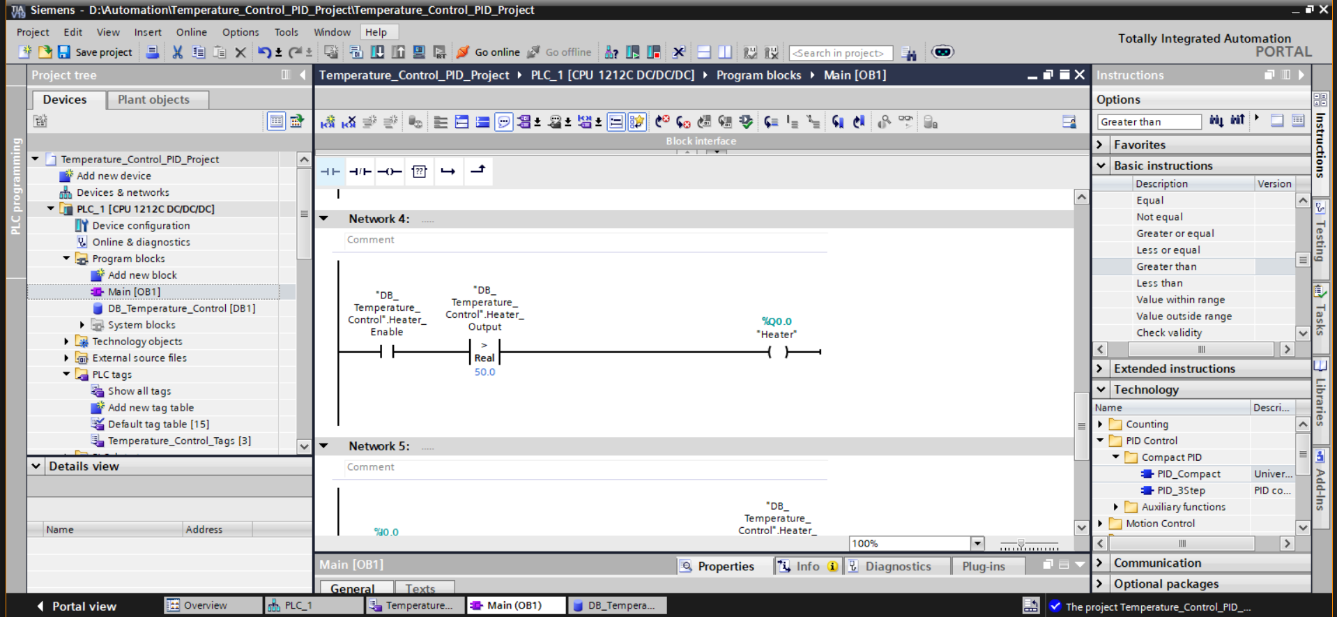
Setpoint, liveTemperature_Cprocess variable, and continuousHeater_Output(%) as the control output; backed by a dedicatedDB_PID_Temperatureinstance Data Block - Threshold-Based Actuation — PID output compared against a 50% threshold via a Real greater-than comparator; drives
%Q0.0 "Heater"as a discrete on/off output from a continuous control signal - Emergency Stop Interlock —
%I0.0 "E_Stop"NC contact in series with the heater output rung; de-energizes the heater immediately and unconditionally on activation - Overtemperature Safety Cutout — independent comparator monitors
Temperature_Cagainst a 90.0 °C ceiling; disablesHeater_Enablewhen the limit is exceeded, preventing the heater from being re-energized until the process cools below the threshold - Data Block Architecture — all internal program variables (
Temperature_Norm,Temperature_C,Setpoint,Heater_Output,Alarm_High,Alarm_Low,Heater_Enable,E_Stop) declared inDB_Temperature_Control [DB1]with no hardware addresses, separating I/O from internal logic state - Alarm Flag Generation — latched
Alarm_HighandAlarm_Lowboolean flags derived from process variable bounds, accessible to operator monitoring interfaces
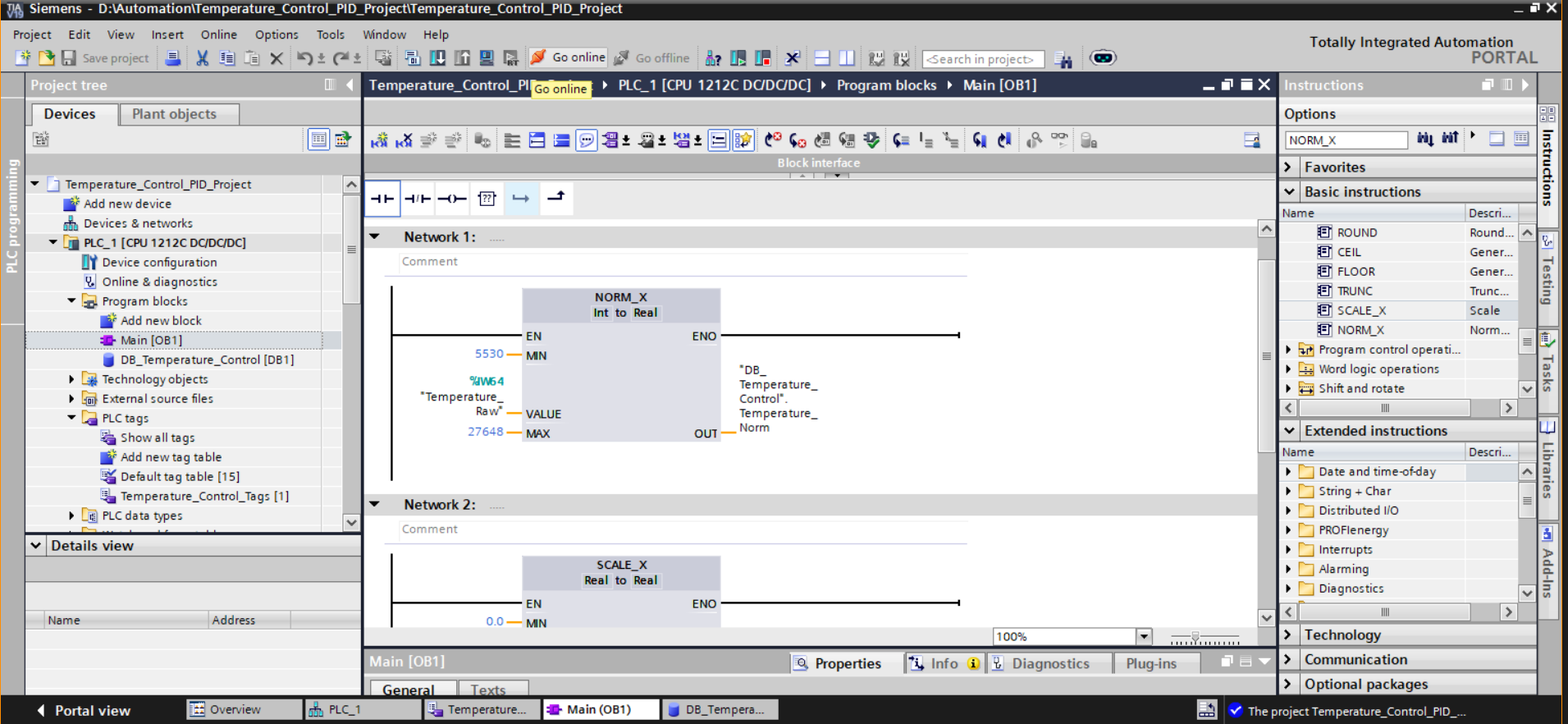
The signal conditioning pipeline is structured as two sequential function block
networks: NORM_X in Network 1 produces a dimensionless ratio from the
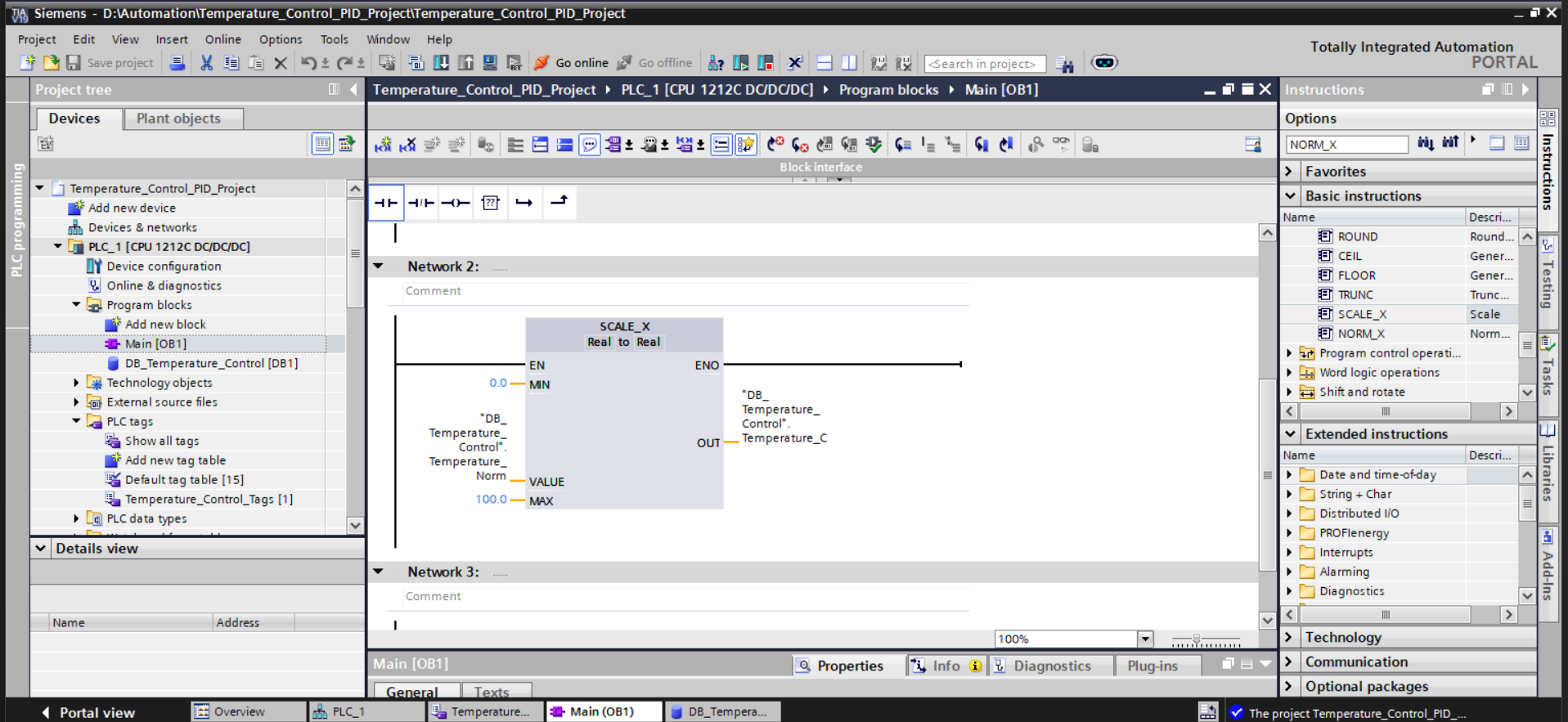
raw integer, and SCALE_X in Network 2 maps that ratio to the
configured engineering range. This separation makes the scaling parameters
independently adjustable and keeps the normalization and range mapping concerns
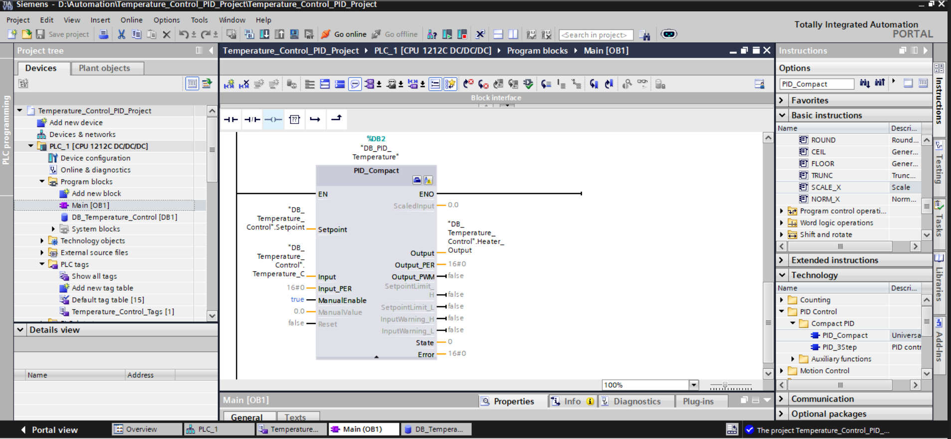
explicit rather than embedded in a single expression. The PID block in Network 3
receives the fully conditioned process variable and writes its output directly to
the DB_Temperature_Control.Heater_Output tag, which is then consumed
downstream by the actuation and safety networks.
Project Screenshots
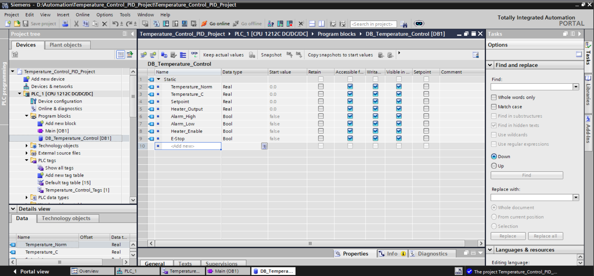

Data Block Variables
DB_Temperature_Control [DB1] — Static Variables

Name               Data Type    Start Value    Description
─────────────────────────────────────────────────────────────────────
Temperature_Norm   Real         0.0            Normalized ratio from NORM_X (0.0–1.0)
Temperature_C      Real         0.0            Scaled process variable in °C (0.0–100.0)
Setpoint           Real         0.0            Operator-configured temperature target, °C
Heater_Output      Real         0.0            PID_Compact continuous output (0.0–100.0 %)
Alarm_High         Bool         false          Process variable above configured high limit
Alarm_Low          Bool         false          Process variable below configured low limit
Heater_Enable      Bool         false          Safety gate: FALSE if E-Stop or overtemp active
E_Stop             Bool         false          Emergency stop status (latched from %I0.0)
Control Flow Architecture
%IW64 (Raw Analog: 0–27648)
        │
        ▼
  [NORM_X — Int to Real]
  MN: 0 / MAX: 27648
  OUT → Temperature_Norm (0.0–1.0)
        │
        ▼
  [SCALE_X — Real to Real]
  MN: 0.0 / MAX: 100.0
  OUT → Temperature_C (°C)
        │
        ▼
  [PID_Compact — DB_PID_Temperature]
  Setpoint ← DB.Setpoint
  Input    ← DB.Temperature_C
  Output   → DB.Heater_Output
        │
        ▼
  [Comparator: Heater_Output > 50.0]
        │
        ▼
  [Safety Gate]
  E_Stop (NC) AND Temperature_C < 90.0
        │
        ▼
  %Q0.0 "Heater" (Discrete Output)
Testing & Validation
Validation was conducted against the TIA Portal soft-PLC runtime in online mode, using forced variable injection to simulate field conditions — analog input values, setpoint changes, emergency stop activation — without requiring physical hardware in the loop. Each network was exercised in isolation before end-to-end integration testing confirmed correct behavior across the full signal chain.
- NORM_X and SCALE_X outputs verified across the full input range (0, 13824, and 27648 raw → 0 °C, 50 °C, 100 °C) using online monitoring with forced variable values
- PID_Compact confirmed operational by observing
Heater_Outputresponding to setpoint changes and process variable deviations; State output monitored to confirm the block was in active closed-loop mode rather than initialization or error state - Threshold comparator correctly energized
%Q0.0whenHeater_Outputexceeded 50.0% and de-energized below; no spurious transitions observed at the boundary under steady-state conditions - E-Stop interlock immediately dropped
Heater_Enableand de-energized the heater output on%I0.0activation, independent of PID output value or current comparator state - Overtemperature cutout suppressed
Heater_Enablewhen forcedTemperature_Cexceeded 90.0 °C;Heater_Enablerestored automatically once the value fell below the threshold with E-Stop cleared - Data Block variable access confirmed correct across all networks — no address conflicts or DB access errors observed in the diagnostic panel during online operation
Challenges Faced
The most significant technical obstacle was the architectural distinction between
PLC tags and Data Block variables in TIA Portal. The tag table editor enforces
hardware address assignment for all declared tags; attempting to declare internal
program variables there produced address conflicts and compilation errors. The
resolution — moving all internal state to a structured DB — required understanding
that TIA Portal's execution model separates I/O-mapped memory from instance and
global data memory, and that DB.VariableName dot-notation is the
correct access path for DB-resident values from ladder rungs and function block inputs.
A second challenge was correctly wiring the PID_Compact technology
object. The block exposes a large parameter surface with non-obvious naming
conventions (Input for the process variable, Output for
the control effort, ManualEnable and ManualValue for
feedforward override) and requires an associated instance DB that TIA Portal
auto-generates. Mapping these pins correctly to the right internal variables —
and distinguishing which outputs were diagnostics versus actionable control
signals — required careful cross-referencing of the technology object documentation.
A subtler issue appeared in the safety comparator logic: an initial implementation used a greater-than comparison for the overtemperature cutout where a less-than was required, producing inverted safety behavior (heater enabled above the limit, disabled below). Catching this required tracing the rung logic systematically from output back to conditions, reinforcing the value of verifying each network's logical intent against its implementation independently before integration.
Key Learning Outcomes
- Siemens TIA Portal project architecture — device configuration, program blocks, tag tables, Data Blocks, and Technology Objects as distinct layers in the project tree
- 4–20 mA analog signal conditioning pipeline using
NORM_XandSCALE_Xwith correct data type handling (Int → Real conversion at the normalization stage) - PID_Compact technology object instantiation — instance DB creation, process variable and setpoint wiring, output routing, and mode management via
ManualEnable - Architectural separation of I/O tags from internal program variables using global Data Blocks, and the access semantics for DB-resident values from ladder logic
- Industrial safety interlock design: NC contact logic for emergency stop, independent overtemperature comparator as a non-bypassable safety layer, and correct Boolean gating of actuator outputs
- Ladder Diagram comparator instructions (greater-than, less-than) applied to Real-type process variables for threshold-based output switching from continuous control signals
- Online monitoring and forced variable injection as a validation methodology for PLC logic in the absence of physical hardware
Tools Used
- Siemens TIA Portal V17 (Totally Integrated Automation Portal)
- Siemens S7-1212C DC/DC/DC PLC (CPU 1212C)
- IEC 61131-3 Ladder Diagram (LD)
- PID_Compact Technology Object (Siemens Compact PID)
- NORM_X / SCALE_X standard function blocks for analog signal conditioning
- TIA Portal online simulation with forced variable injection for hardware-in-the-loop-free validation