Case Study: PLC Tank Level Controller with Fault Detection
An automated tank filling and draining system with timeout-based fault detection, built using OpenPLC Editor and IEC 61131-3 Structured Text (ST)
Project Overview
This project implements a sensor-driven closed-loop tank level control system representative of industrial process automation applications in water treatment, chemical dosing, and fluid handling environments. The controller monitors two discrete level sensor inputs to govern fill valve actuation and drain pump operation, maintains internal filling state across scan cycles, and employs a TON timer instance to enforce a maximum permissible fill duration. If the high-level sensor fails to assert within the defined timeout window, a latched fault condition is raised, all process outputs are de-energised, and operator intervention via a manual reset input is required before normal operation can resume. The entire solution was authored in IEC 61131-3 Structured Text within OpenPLC Editor and verified through live simulation and forced-variable testing.
Problem
Automated tank level control requires the system to react deterministically to sensor state changes while simultaneously protecting against process anomalies that sensors alone cannot resolve. A fill valve that remains open indefinitely — due to a slow inlet, blocked supply line, sensor failure, or valve fault — will cause tank overflow and potential equipment damage. The control system must therefore implement a watchdog mechanism that monitors fill duration independently of sensor feedback, assert a latched fault alarm when the timeout threshold is exceeded, and suppress all further output activation until an operator explicitly acknowledges and clears the fault condition. Designing this behaviour correctly within the PLC scan cycle model, without introducing race conditions between the timer, the fault latch, and the reset logic, was the core engineering requirement of this project.
Solution
- LowLevelSensor — Digital BOOL input; asserts when tank level drops below the minimum threshold, initiating the fill sequence by setting
FillingActive— provided no latched fault is present - HighLevelSensor — Digital BOOL input; asserts when the tank reaches its target fill level, de-asserting
FillingActiveand terminating the fill cycle; simultaneously drivesDrainPumpoutput to manage overflow margin - FillValve — Discrete BOOL output; driven directly by
FillingActive— open only when filling is active and no fault condition is latched - DrainPump — Discrete BOOL output; asserted whenever
HighLevelSensoris active, providing level regulation above the high setpoint - FillTimer (TON) — IEC 61131-3 On-Delay timer instance; accumulates elapsed time while
FillingActiveis TRUE; its.Qoutput asserts after a 10-second preset, triggering fault detection logic - FaultAlarm — Discrete BOOL output; driven by the
FillFaultinternal latch register; remains asserted after a timeout event until explicitly cleared by operator reset - ResetFaultButton — Operator BOOL input; evaluated at the top of the scan to synchronously clear
FillFaultandFillingActive, restoring the system to a ready state without requiring a program reload
Structured Text was selected over Ladder Logic for this project due to the precision required in ordering the reset, fill activation, timeout, and output assignment logic within a single scan cycle. Incorrect execution ordering in this type of fault-latching system can produce one-scan glitches where outputs assert briefly before being suppressed by a fault condition detected later in the same rung network. Structured Text's top-to-bottom sequential execution model eliminates this ambiguity, making scan-cycle behaviour fully predictable and auditable.
Project Screenshots
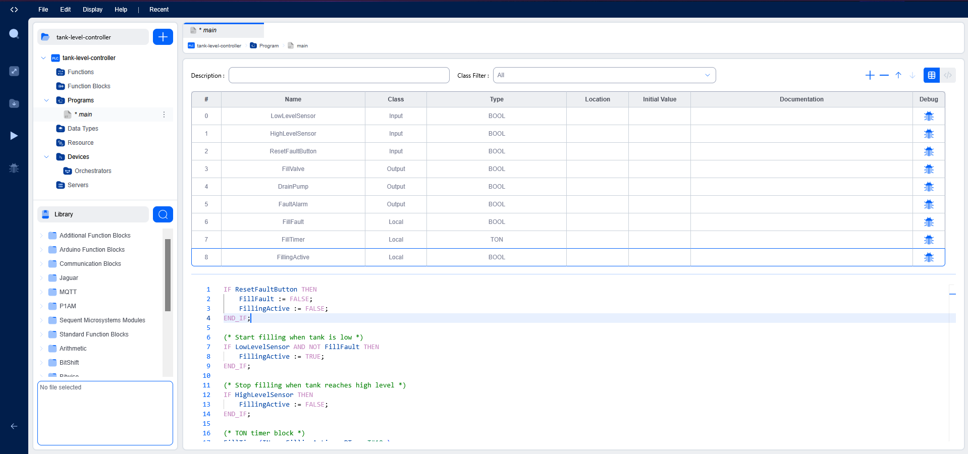
Variables Used
VAR_INPUT
    LowLevelSensor    : BOOL;
    HighLevelSensor   : BOOL;
    ResetFaultButton  : BOOL;
END_VAR

VAR_OUTPUT
    FillValve         : BOOL;
    DrainPump         : BOOL;
    FaultAlarm        : BOOL;
END_VAR

VAR
    FillFault         : BOOL;
    FillingActive     : BOOL;
    FillTimer         : TON;
END_VAR
Structured Text Logic
IF ResetFaultButton THEN
    FillFault := FALSE;
    FillingActive := FALSE;
END_IF;

IF LowLevelSensor AND NOT FillFault THEN
    FillingActive := TRUE;
END_IF;

IF HighLevelSensor THEN
    FillingActive := FALSE;
END_IF;

FillTimer(IN := FillingActive, PT := T#10s);

IF FillTimer.Q THEN
    FillFault := TRUE;
    FillingActive := FALSE;
END_IF;

FillValve := FillingActive;
FaultAlarm := FillFault;

IF HighLevelSensor THEN
    DrainPump := TRUE;
ELSE
    DrainPump := FALSE;
END_IF;
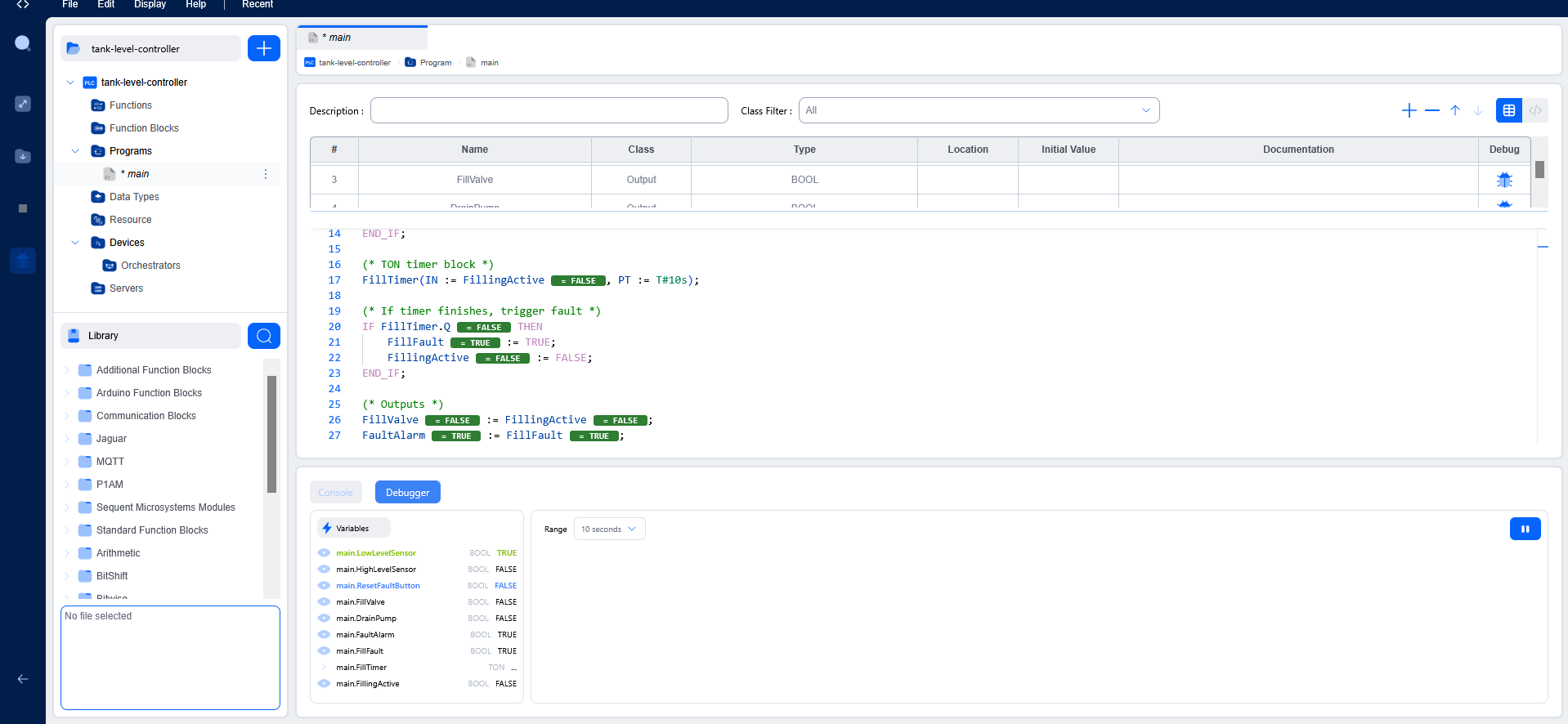
Testing & Debugging
System validation was performed within the OpenPLC runtime environment using the integrated simulator and real-time variable debugger. All sensor inputs were exercised via forced-variable injection to replicate field conditions across normal operation, high-level cutoff, fault timeout, and fault recovery scenarios. The following test cases were executed and confirmed:
LowLevelSensorwas forced HIGH with no active fault —FillingActiveset correctly andFillValveasserted within the same scan cycleHighLevelSensorwas forced HIGH mid-fill —FillingActivecleared,FillValvede-asserted, andDrainPumpactivated correctly without output overlapFillTimerwas allowed to accumulate withHighLevelSensorheld LOW —.Qasserted at the 10-second mark, latchingFillFaultTRUE and de-assertingFillingActiveandFillValvein the same scanFaultAlarmremained asserted across subsequent scan cycles with no further input changes, confirming correct fault latching behaviourLowLevelSensorwas re-asserted whileFillFaultwas active — confirmed that theNOT FillFaultguard condition correctly blocked fill re-activationResetFaultButtonwas forced HIGH —FillFaultandFillingActivecleared synchronously within the same scan,FaultAlarmde-asserted, and the system returned to a ready state available for the next fill cycle
Challenges Faced
The primary technical challenge was understanding and correctly managing TON timer instance state within the OpenPLC scan cycle. During early development, the FillTimer instance continued accumulating elapsed time after FillingActive had been cleared by a fault condition, because the timer's IN pin was not being explicitly driven to FALSE in the same scan the fault was detected. This caused the timer to assert .Q on subsequent scans even after a successful reset, re-triggering the fault latch immediately after the operator cleared it. The fix required ensuring FillingActive — which directly drives the timer's IN pin — was set to FALSE before the timer call in execution order, so the TON instance received a de-asserted IN signal in the same scan the fault was latched.
A secondary challenge was correctly sequencing the reset logic relative to the fill activation and fault detection blocks. Placing the ResetFaultButton evaluation after the fault detection block allowed a one-scan window where both the reset and a re-triggered fault could coexist, producing unreliable recovery behaviour. Moving the reset block to the top of the program — ensuring it executes first in every scan — resolved this and made fault recovery deterministic. This experience provided a concrete and practical understanding of how scan-cycle execution order directly determines system behaviour in IEC 61131-3 PLC programs.
Key Learning Outcomes
- Sensor-driven closed-loop process control — translating discrete level sensor inputs into conditional output actuation within a real PLC scan cycle model
- IEC 61131-3 Structured Text programming — conditional logic, internal state management, and scan-cycle-aware execution ordering
- TON timer instance behaviour — managing
INpin state, elapsed time accumulation, and.Qassertion timing across scan cycles in a fault-detection context - Fault latching and operator reset logic — designing latched fault states that suppress process resumption until explicit acknowledgement, and structuring reset logic for deterministic scan-cycle recovery
- Tank and fluid level automation — applying setpoint-based sensor logic to govern fill and drain actuator outputs in a closed-loop control architecture
- Industrial debugging techniques — tracing internal state variables (
FillFault,FillingActive) rather than relying solely on output observation to diagnose scan-cycle-level timing anomalies
Tools Used
- OpenPLC Editor — IEC 61131-3 compliant PLC development environment
- Autonomy Edge — Industrial automation platform
- Structured Text (ST) — IEC 61131-3 high-level PLC programming language
- OpenPLC Runtime Simulator and Variable Debugger