Siemens Smart Solar Plant
SCADA System
Phase 3 elevates the virtualised S7-1500 renewable energy platform into a fault-aware industrial SCADA system by engineering a centralised alarm management architecture, operator-driven fault injection controls, and automated safe-state protection logic. The system now operates as a realistic, monitored solar installation capable of detecting abnormal plant conditions, executing deterministic protective fallback transitions, and presenting live alarm annunciation through a dedicated WinCC Advanced HMI diagnostics panel — consistent with alarm handling frameworks deployed in utility-scale automation environments.
Phase Objective
Phase 2 delivered a fully operational intelligent energy management layer with live SCADA visualisation. Phase 3 extends that foundation by introducing the industrial alarm management subsystem — the protection and diagnostics layer that transforms a monitoring platform into a fault-resilient, self-protecting plant controller.
The primary engineering objective was to implement a production-representative alarm management pipeline: centralised fault state storage, structured alarm classification, automated safe-state actuation, emergency reserve activation, and operator-accessible fault injection — all integrated directly into the existing Phase 2 energy routing architecture without disrupting established control logic. The result is a platform that detects, classifies, communicates, and responds to abnormal operating conditions across every PLC scan cycle.
Software Environment
| Component | Technology |
|---|---|
| PLC Platform | Siemens S7-1500 (CPU 1511-1 PN) |
| Engineering Environment | TIA Portal V19 |
| Simulation Runtime | Siemens PLCSIM V19 |
| Programming Language | SCL (Structured Control Language) |
| HMI / SCADA Platform | WinCC Advanced Runtime (V19) |
| HMI Hardware Target | TP700 Comfort Panel (virtualised) |
Extended System Architecture — Phase 3
Phase 3 appends a dedicated alarm processing layer above the Phase 2 efficiency metrics engine. The alarm manager executes as the final processing stage in each OB1 scan cycle, consuming both raw fault injection inputs from HMI operator commands and resolved energy routing states from upstream blocks — ensuring all protection logic operates on fully updated plant data before issuing safe-state commands.
Phase 3 Program Block Structure
One new function block and one dedicated alarm data block were introduced in Phase 3. The alarm manager is positioned as Network 8 in the OB1 execution sequence — downstream of all energy routing and metrics computation, guaranteeing it consumes fully resolved plant state data on every scan.
Network 1  — FB_WeatherEngine        [FB1 / DB6]  — Phase 1
Network 2  — FB_SolarArray           [FB2 / DB7]  — Phase 1
Network 3  — FB_BatterySystem        [FB3 / DB8]  — Phase 1
Network 4  — FB_LoadDemand           [FB5 / DB12] — Phase 2
Network 5  — FB_EnergyRouter         [FB6 / DB13] — Phase 2
Network 6  — Grid SCL Resolution                  — Phase 2
Network 7  — FB_EfficiencyMetrics    [FB7 / DB14] — Phase 2
Network 8  — FB_AlarmManager         [FB8 / DB16] — Phase 3 ★
New System Components — Phase 3
DB_Alarms [DB5] — Centralised Alarm Database
A dedicated alarm data block was engineered to serve as the single authoritative source of all fault states, alarm metadata, and plant protection flags across the entire system. Centralising alarm ownership in a discrete DB eliminates conflicting fault writes from multiple function blocks, simplifies HMI tag binding, and provides a clean scalability path for future alarm expansion phases. All downstream alarm consumers — including the HMI annunciator panel and safe-state logic — read exclusively from this block.
| Variable | Type | Purpose |
|---|---|---|
Fault_Inverter | Bool | Solar inverter failure — disables generation routing |
Fault_BatteryOverTemp | Bool | Battery thermal protection event — forces safe mode |
Fault_CloudSpike | Bool | Sudden irradiance collapse — generation degradation alarm |
Fault_GridBlackout | Bool | Utility grid outage — activates emergency reserve |
Fault_Overload | Bool | Excessive plant demand — triggers overload protection |
AlarmActive | Bool | Global alarm presence flag — any active fault condition |
AlarmAck | Bool | Operator acknowledgment register |
SafeMode | Bool | Protective fallback operating mode — inhibits charge/discharge |
EmergencyReserve | Bool | Emergency battery reserve activation flag |
ActiveAlarmText | String[80] | Current active alarm descriptor |
AlarmCode | Int | Numerical alarm identifier for historian and SCADA |
WarningLevel | Int | Alarm severity classification (1 = Warning → 3 = Critical) |
FB_AlarmManager [FB8 / DB16] — Centralised Alarm Processing Engine
A structured SCL function block implementing the full alarm lifecycle: detection, classification, active text assignment, alarm code generation, safe-state command issuance, and emergency reserve activation. The block evaluates all configured fault conditions on every PLC scan cycle using a priority-ordered conditional evaluation structure — ensuring that the highest-severity active fault governs the system's protection response at all times. Fault priority is deterministic: Grid Blackout and Battery Overtemperature trigger immediate protective transitions, while lower-severity conditions generate alarms without forcing safe-state actuation.
- Evaluates all five fault inputs on every OB1 scan with deterministic priority ordering
- Assigns
ActiveAlarmText,AlarmCode, andWarningLevelbased on highest-priority active fault - Sets
AlarmActiveglobal flag whenever any fault condition is asserted - Asserts
SafeModeon Battery Overtemperature — inhibits all charge and discharge operations - Asserts
EmergencyReserveon Grid Blackout — activates backup battery reserve dispatch - Clears all protection flags automatically when all fault inputs are deasserted
- Instance DB:
DB_AlarmManager [DB16]
Alarm Classification Matrix:
| Fault Condition | Alarm Code | Warning Level | Automated Protection Response |
|---|---|---|---|
| Grid Blackout | 103 | 3 — Critical | Emergency reserve activation |
| Battery Overtemperature | 102 | 3 — Critical | Safe mode — charge/discharge inhibit |
| Inverter Fault | 101 | 2 — Major | Generation routing disabled |
| Cloud Spike | 104 | 1 — Warning | Generation degradation flagged |
| Overload | 105 | 2 — Major | Overload protection handling |
WinCC Advanced — Fault Injection Panel HMI Screen
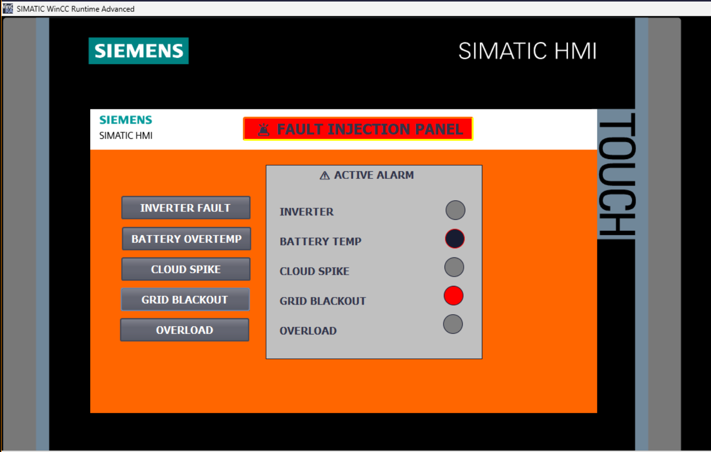
A dedicated diagnostics screen was engineered inside WinCC Advanced Runtime to provide operators with direct runtime control over fault simulation and real-time alarm state visibility. The panel was architecturally isolated from the main SCADA overview screen to maintain clean HMI organisation and prevent screen space contention — a structural decision that also mirrors real commissioning practice, where fault injection and diagnostics panels are always separated from operational overview screens.
- Five operator-triggered fault injection buttons — each writes directly to the corresponding PLC alarm bit in
DB_Alarmsvia HMI-to-PLC tag binding - Live alarm annunciator panel with per-fault indicator circles — animated using WinCC Single Bit visibility mode bound to
PLC_Alarm_Tags - Active alarm status area — reflects
AlarmActiveglobal flag in real time - Colour-coded annunciator indicators: grey (inactive), red (active fault)
- All five fault conditions independently injectable and simultaneously visible during simulation runtime
HMI Tag Table — PLC_Alarm_Tags [5 Tags]:
| HMI Tag Name | Type | PLC Tag Binding |
|---|---|---|
Fault_Inverter_HMI | Bool | DB_Alarms.Fault_Inverter |
Fault_BatteryOverTemp_HMI | Bool | DB_Alarms.Fault_BatteryOverTemp |
Fault_CloudSpike_HMI | Bool | DB_Alarms.Fault_CloudSpike |
Fault_GridBlackout_HMI | Bool | DB_Alarms.Fault_GridBlackout |
Fault_Overload_HMI | Bool | DB_Alarms.Fault_Overload |
Safe-State Protection Logic
The alarm manager implements deterministic safe-state transitions — a mandatory requirement in any industrial automation system where unhandled fault conditions can result in equipment damage or unsafe operational states. The protection logic enforces two distinct fallback modes based on fault severity and type:
- SafeMode — Asserted on thermal protection events. Inhibits all battery charge and discharge command outputs, isolating the BESS from the power bus until fault clearance and operator acknowledgment.
- EmergencyReserve — Asserted on grid outage detection. Activates the battery reserve dispatch path, sustaining critical plant load from stored energy while grid connectivity is unavailable.
- Both protection states resolve automatically when the corresponding fault condition clears — restoring normal operating mode without requiring manual override.
- Protection flag outputs are written to
DB_Alarmsand are visible to both the HMI annunciator and any downstream control logic consuming them in future phases.
Live PLC Runtime Snapshot — DB_Alarms [DB5]
The screenshots below were captured from the active TIA Portal PLCSIM session with FB_AlarmManager executing in real-time. The DB monitor view confirms live alarm processing: Fault_GridBlackout and Fault_BatteryOverTemp are simultaneously active, driving AlarmActive = TRUE, SafeMode = TRUE, EmergencyReserve = TRUE, ActiveAlarmText = 'GRID BLACKOUT', AlarmCode = 103, and WarningLevel = 3 — confirming correct priority-ordered alarm resolution and automated protection response across a concurrent multi-fault scenario.
TIA Portal & WinCC Runtime Screenshots
Four operational screenshots captured from the live Phase 3 commissioning session, demonstrating PLC alarm processing, HMI tag architecture, fault injection panel operation, and live DB monitor alarm state verification.
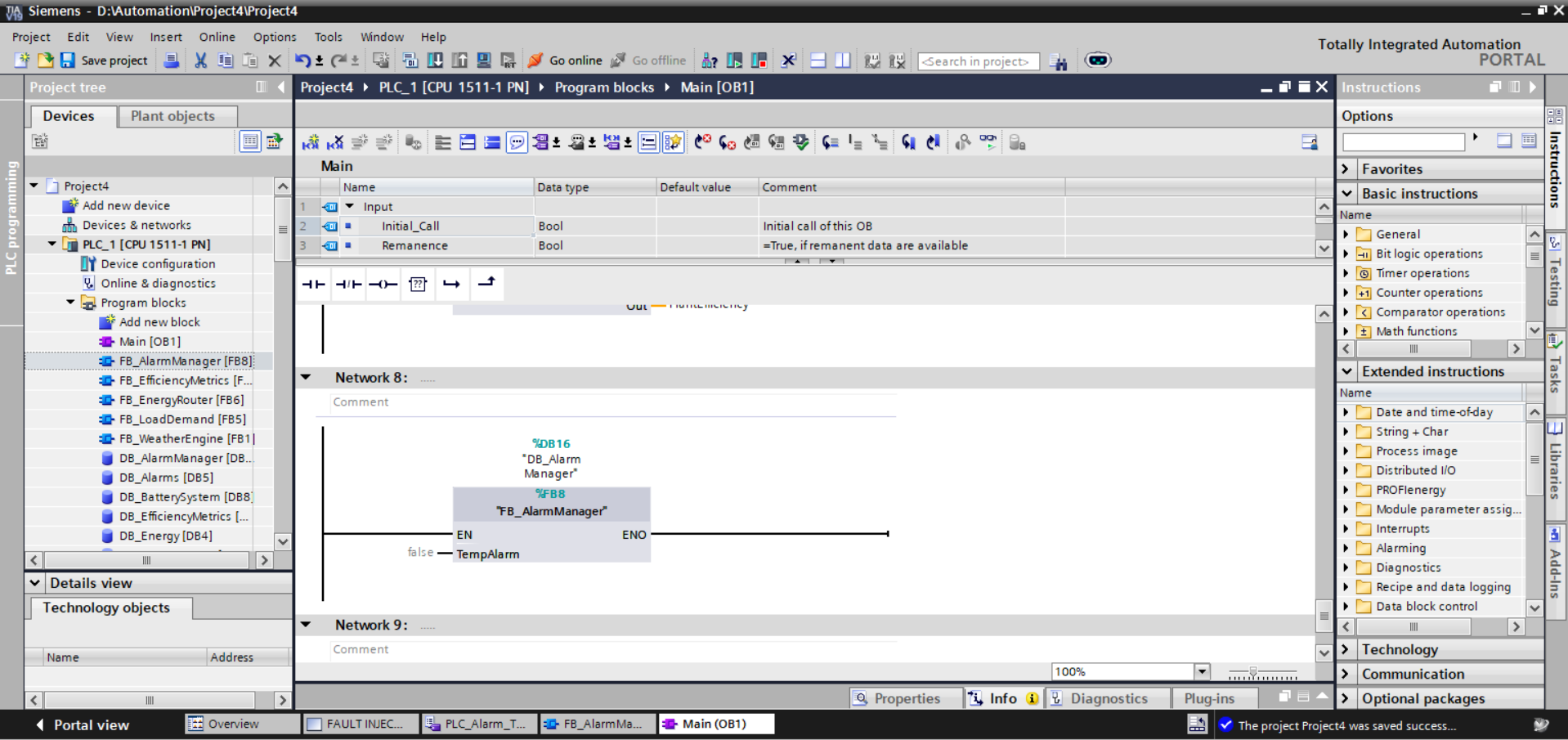
FB_AlarmManager [FB8 / DB16]. Phase 3 alarm processing block integrated as the final network in the OB1 execution sequence. Instance DB DB_AlarmManager [DB16] bound with TempAlarm input. Project tree confirms full Phase 3 block complement: FB_AlarmManager, DB_AlarmManager [DB16], and DB_Alarms [DB5] alongside all Phase 1–2 blocks. Project saved successfully to PLCSIM runtime — zero compile errors confirmed.
![HMI Tag Table — PLC_Alarm_Tags [5]](../assets/Screenshot_2026-05-10_225110.png)
PLC_Alarm_Tags [5] tag table. All five fault injection HMI tags defined and bound: Fault_Inverter_HMI, Fault_BatteryOverTemp_HMI, Fault_CloudSpike_HMI, Fault_GridBlackout_HMI, Fault_Overload_HMI — each typed as Bool with HMI_Connection binding to PLC_1 and fully qualified DB_Alarms path references. Tag table integrated under HMI_1 [TP700 Comfort] alongside the Default tag table [16] from Phase 2.
![DB_Alarms [DB5] Live Monitor — Multi-Fault Active State](../assets/Screenshot_2026-05-10_235042.png)
DB_Alarms [DB5] Multi-fault active state: Fault_BatteryOverTemp = TRUE, Fault_GridBlackout = TRUE. Automated protection responses confirmed: AlarmActive = TRUE, SafeMode = TRUE, EmergencyReserve = TRUE. Priority alarm resolution: ActiveAlarmText = 'GRID BLACKOUT', AlarmCode = 103, WarningLevel = 3. Highlighted orange rows indicate variables with monitor values deviating from start values — confirming live FB_AlarmManager execution modifying DB state in real time.
Virtual Commissioning & Runtime Status
All Phase 3 blocks compiled to zero errors under TIA Portal V19 and downloaded to the PLCSIM CPU 1511-1 PN virtual runtime. The WinCC Advanced HMI project was synchronised via the integrated HMI connection and launched in Runtime Advanced with all five PLC_Alarm_Tags confirmed active. DB monitor verification confirmed FB_AlarmManager correctly modifying DB_Alarms monitor values in real time during multi-fault injection scenarios.
Integration Issues & Resolutions
Four non-trivial engineering challenges were encountered and systematically diagnosed during Phase 3 implementation — each yielding reusable lessons applicable to production SCADA alarm commissioning.
⚠ Issue 1 — HMI Tag Type Incompatibility: String[80] Binding Failure
Binding the ActiveAlarmText String[80] PLC variable directly to standard WinCC object types triggered compilation failures. WinCC Advanced imposes type constraints on which display object types can accept string tag bindings — attempting to bypass this with unsupported object pairings produced non-recoverable compilation errors that blocked runtime launch.
Resolution: The design was restructured to use dedicated boolean annunciator indicators bound to individual fault tags rather than a dynamic string display field. This approach is more architecturally robust — boolean annunciators update faster, are fully compatible with WinCC animation frameworks, and eliminate the string length dependency entirely.
⚠ Issue 2 — Alarm Annunciator Circles Permanently Visible
Initial configuration of the HMI annunciator indicator circles resulted in all five indicators remaining permanently visible regardless of the underlying PLC alarm bit state. Root cause: WinCC visibility animation had been incorrectly configured — animation mode, bit value trigger, and tag binding were not aligned to produce boolean-driven show/hide behaviour.
Resolution: Visibility animations were reconfigured to Single Bit mode with Bit value = 1 and explicit binding to the correct PLC_Alarm_Tags boolean entries. This configuration correctly gates circle visibility to the asserted state of each fault bit, producing accurate per-fault annunciation at runtime.
⚠ Issue 3 — Fault Buttons Non-Functional After Logic Update
Following modification of FB_AlarmManager SCL logic and recompilation, the HMI fault injection buttons appeared non-functional — operator presses produced no observable change in PLC alarm state. Root cause: the updated PLC program had not been downloaded to the PLCSIM virtual CPU after compilation; the runtime was still executing the previous program image.
Resolution: Full recompilation of the PLC program followed by explicit download to the PLCSIM runtime CPU before launching WinCC Runtime Advanced. This confirmed the standard commissioning discipline: any PLC logic change requires a complete download cycle before HMI interaction testing is valid.
⚠ Issue 4 — HMI Screen Space Constraints: Alarm Panel Overcrowding
The existing Phase 2 SCADA overview screen — carrying weather data, energy flow topology, KPI bar, battery gauge, and grid panels — had insufficient available space to accommodate a full alarm annunciator section alongside fault injection controls without creating an unacceptably cluttered operator interface.
Resolution: A dedicated FAULT INJECTION PANEL screen was engineered as a separate WinCC screen, isolating all alarm diagnostics and annunciation into a purpose-built operator view. This architectural decision mirrors industrial HMI design conventions, where alarm and diagnostics panels are always separated from primary process overview screens to maintain operational clarity and reduce cognitive load on operators during fault conditions.
Engineering Lessons — Phase 3
✔ Alarm Systems Demand Centralised Ownership
Separating all fault state variables, alarm metadata, and protection flags into a single dedicated data block — DB_Alarms [DB5] — eliminated all risk of conflicting writes from multiple function blocks competing for the same alarm variables. In multi-block automation architectures, centralised alarm ownership is not a convenience preference — it is a correctness requirement. Distributed alarm state across multiple DBs produces indeterminate HMI annunciation and makes fault isolation exponentially harder at scale.
✔ HMI Fault Injection Panels Are a Production-Grade Commissioning Tool
The operator-driven fault injection panel transformed protection system validation from manual DB forcing in TIA Portal into structured, reproducible runtime testing. This workflow directly replicates how commissioning engineers validate protection systems in real utility-scale installations — fault scenarios are injected through operator interfaces, not debugger interventions. Building this capability into the simulation environment from Phase 3 onward establishes a permanent, realistic test infrastructure for all subsequent alarm and protection development.
✔ Safe-State Logic Is a Non-Negotiable Automation Requirement
A fault detection system that identifies abnormal conditions but issues no protective response is operationally incomplete and potentially dangerous. The deterministic SafeMode and EmergencyReserve transitions implemented in FB_AlarmManager ensure the plant always transitions to a known-safe operating configuration during critical fault events — regardless of HMI operator response time. Automated safe-state actuation is what separates an alarm notification system from a genuine plant protection system.
✔ PLC-HMI Tag Consistency Is a First-Class Engineering Discipline
Multiple integration failures during Phase 3 — including the String[80] binding failure and the visibility animation misconfiguration — originated not from SCL logic errors but from mismatches between PLC data model definitions and HMI tag configurations. In industrial SCADA systems, the tag interface between PLC and HMI must be treated as a formal, validated engineering boundary — not an implementation detail. Tag name consistency, data type alignment, and path accuracy must be verified against the PLC data model before any HMI animation or binding configuration is finalised.
✔ Modular Function Block Architecture Isolates Fault Domains
Encapsulating the entire alarm management pipeline within a single, self-contained FB_AlarmManager block — independent of energy routing and generation logic — meant that every Phase 3 integration issue could be diagnosed and resolved within a precisely bounded scope. No alarm logic change required touching Phase 1 or Phase 2 blocks. This separation of concerns is what makes layered industrial automation platforms debuggable at scale: each functional domain owns its logic, its data, and its failure modes.
Phase 3 System Capabilities
- Simulates five independent industrial plant fault conditions via operator-driven HMI injection
- Executes centralised alarm management — detection, classification, and metadata assignment on every PLC scan
- Applies deterministic priority-ordered alarm resolution across concurrent multi-fault scenarios
- Issues automated SafeMode protection — inhibiting battery charge/discharge during thermal fault conditions
- Issues automated EmergencyReserve activation — dispatching backup battery capacity during grid blackout events
- Generates numerical alarm codes and severity classification levels for historian and SCADA consumption
- Maintains
ActiveAlarmText— human-readable active alarm descriptor updated in real time - Provides live alarm annunciation in WinCC Advanced Runtime via boolean-driven indicator animation
- Integrates alarm processing cleanly into the existing Phase 2 energy routing architecture — zero disruption to established control logic
- Operates entirely within the PLCSIM virtualised commissioning environment — no physical hardware required
Development Roadmap
✅ Phase 1 — Core Simulation
Weather engine, solar generation, BESS, grid manager, PLCSIM virtual commissioning. Complete.
✅ Phase 2 — Advanced Energy Management
Dynamic load demand, intelligent energy routing, efficiency KPIs, WinCC Advanced SCADA HMI. Complete.
🚨 Phase 3 — Alarm & Fault Management
Centralised alarm database, FB_AlarmManager, fault injection panel, safe-state protection, WinCC annunciation. Complete.
Phase 4 — Historical Trends
Energy historian, 24h accelerated playback, trend logging and SCADA reporting dashboards.
Phase 5 — Hybrid Microgrid
Wind turbine simulation, diesel generator backup logic, automatic transfer switching and source priority management.
Phase 6 — Advanced Control
Full plant state machines, PID thermal regulation, predictive energy optimisation, operational recipes.