Case Study: PLC Flashing Warning Beacon with Timer Modes
A cyclic timer-driven industrial warning beacon system implemented in Ladder Logic (LD) using OpenPLC Editor, featuring dual-mode flash rate control via chained TON timer blocks
Project Overview
This project implements a configurable flashing warning beacon using IEC 61131-3 Ladder Logic (LD), designed and simulated in the OpenPLC Editor environment. The core timing mechanism relies on two chained TON (Timer On-Delay) function blocks to generate a continuous, non-blocking pulse cycle with independently configurable ON and OFF durations. The system supports two operational modes: a standard periodic flash for general machine status indication, and an accelerated alarm flash mode that increases pulse frequency to communicate elevated fault urgency. Internal state management is handled via a dedicated boolean flag, FLASH_STATE, which coordinates timer reset sequencing to maintain cycle integrity without race conditions.
Problem
Industrial environments require reliable, unambiguous visual signaling to communicate machine states to operators on the floor. A static indicator is insufficient for time-critical fault conditions, as it fails to attract attention amid busy surroundings. The challenge was to implement a beacon control system that could produce a continuous, self-sustaining flash cycle using only on-delay timers — without relying on external pulse generators or hardware-specific function blocks — while also supporting a dynamically switchable alarm mode that increases urgency signaling without requiring a program halt or re-upload to the PLC.
Solution
- SYSTEM_ENABLE — Digital input acting as the master enable gate; no timer logic executes while de-asserted
- ALARM_MODE — Digital input that switches timer preset values to a shorter cycle duration, increasing flash frequency for fault-priority indication
- WARNING_BEACON — Digital output coil driving the beacon lamp; energised only when
FLASH_STATEis TRUE andSYSTEM_ENABLEis asserted - TIMER_ON — TON instance controlling the beacon ON duration; its completion bit triggers the OFF phase and resets
FLASH_STATE - TIMER_OFF — TON instance controlling the beacon OFF duration; its completion bit re-asserts
FLASH_STATEand restarts the ON phase - FLASH_STATE — Internal boolean used as a sequencing flag to arbitrate between the ON and OFF timer phases, preventing simultaneous timer activation
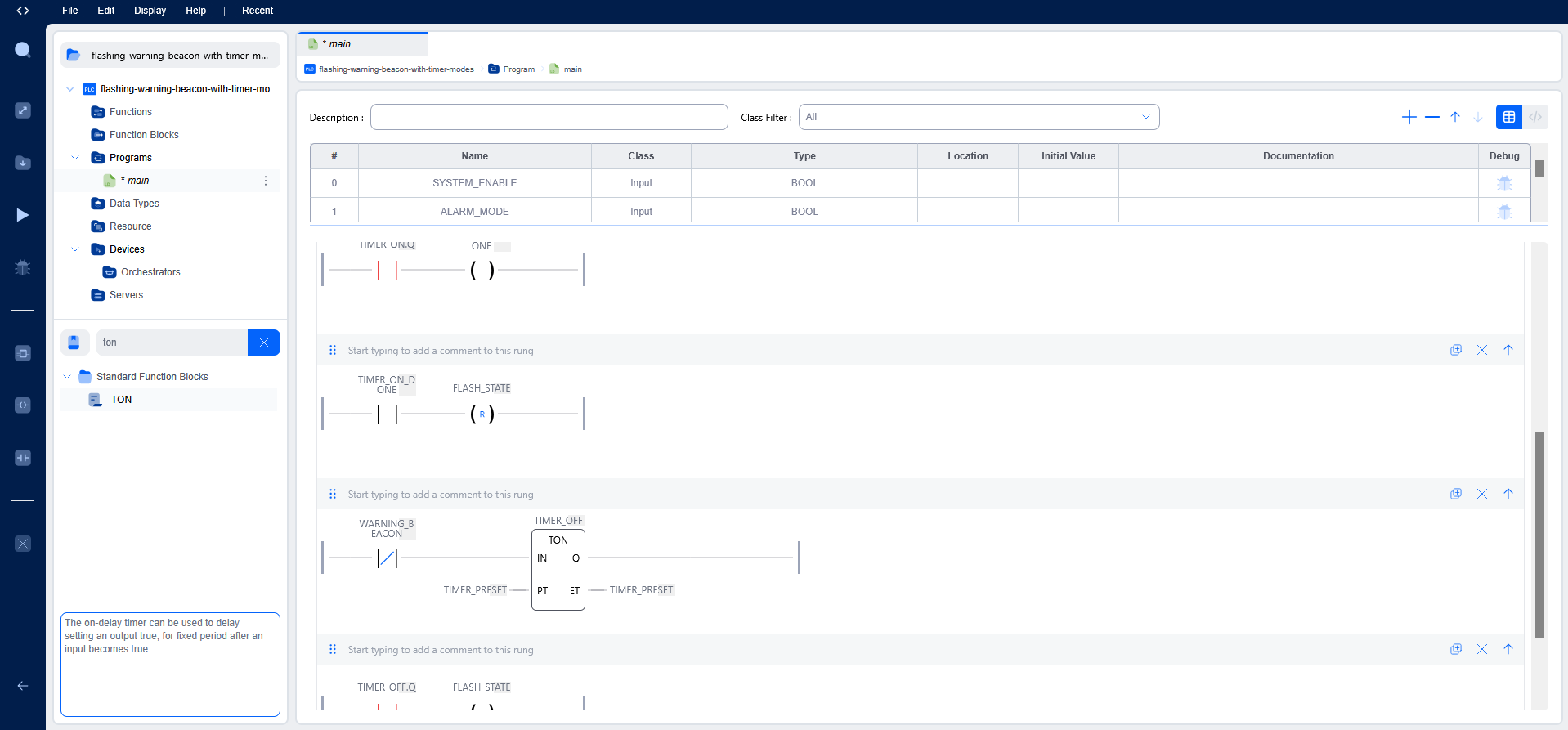
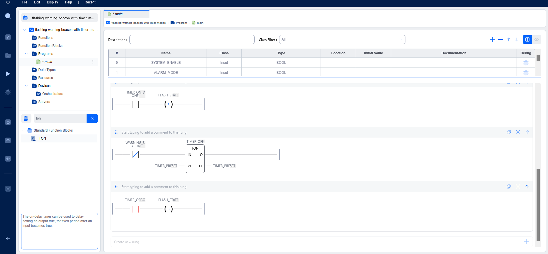
The pulse generation logic is built around a two-stage timer chain. When SYSTEM_ENABLE is asserted and FLASH_STATE is FALSE, TIMER_OFF begins accumulating. On its done output, FLASH_STATE is set TRUE, which simultaneously de-energises TIMER_OFF (resetting it) and enables TIMER_ON. When TIMER_ON completes, FLASH_STATE is cleared, returning the system to the OFF phase and completing one full cycle. This handoff pattern ensures that only one timer is active at any given scan, eliminating state overlap. The ALARM_MODE input is evaluated before each timer enable rung to conditionally substitute a shorter preset value, allowing the flash rate to increase without interrupting the current cycle.
Project Screenshots
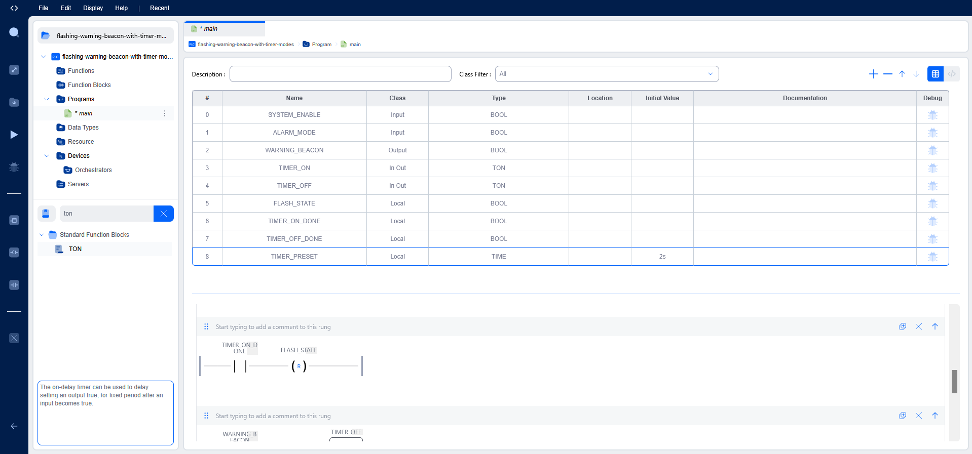
Variables Used
VAR_INPUT
    SYSTEM_ENABLE : BOOL := FALSE;
    ALARM_MODE    : BOOL := FALSE;
END_VAR

VAR_OUTPUT
    WARNING_BEACON : BOOL := FALSE;
END_VAR

VAR
    TIMER_ON        : TON;
    TIMER_OFF       : TON;
    FLASH_STATE     : BOOL := FALSE;
    TIMER_ON_DONE   : BOOL := FALSE;
    TIMER_OFF_DONE  : BOOL := FALSE;
    TIMER_PRESET    : TIME := T#2s;
END_VAR
Testing & Debugging
Functional verification was carried out using the integrated OpenPLC soft PLC simulator with the built-in variable watch and debugger. Each scan cycle was monitored in real time to confirm correct timer accumulation, done-bit assertion timing, and state flag transitions. The following conditions were explicitly validated:
- Asserting
SYSTEM_ENABLEcorrectly initiates the OFF phase and begins the first timer accumulation cycle - The
WARNING_BEACONoutput coil energises and de-energises in strict synchronisation withFLASH_STATEtransitions FLASH_STATEtoggles cleanly between TRUE and FALSE with no spurious intermediate states observed across extended simulation runs- Asserting
ALARM_MODEmid-cycle correctly applies the reduced preset value on the next timer enable, increasing flash frequency without stalling the cycle - De-asserting
SYSTEM_ENABLEhalts all timer activity and forcesWARNING_BEACONto de-energise within a single scan
Challenges Faced
The primary engineering challenge was designing a self-resetting timer loop that avoids simultaneous timer activation within a single scan cycle. In Ladder Logic, TON blocks begin accumulating immediately when their enable coil is TRUE; without careful state sequencing, both timers could activate concurrently, producing undefined flash behaviour. This was resolved by using FLASH_STATE as a mutual exclusion flag — each timer's enable rung is conditioned on the inverse state of the other, ensuring only one timer accumulates at any given time.
A secondary challenge was implementing alarm mode preset switching without introducing transient glitches. Because TON timers retain their elapsed value when their enable drops momentarily, any brief de-assertion during a preset swap would cause an incorrect accumulated time on resumption. This was addressed by evaluating the ALARM_MODE input prior to each timer enable evaluation within the same scan, so the preset is applied consistently without interrupting the active timer.
Key Learning Outcomes
- Practical application of IEC 61131-3 TON function blocks and accumulated timing behaviour across scan cycles
- Design of self-resetting cyclic timer chains for pulse generation without dedicated oscillator function blocks
- State-based sequencing using internal boolean flags to enforce mutual exclusion between timer phases
- Runtime preset modification for multi-mode timing behaviour without program interruption
- PLC soft simulation methodology: variable watching, scan-by-scan debug, and output coil verification
- Industrial warning system design principles, including urgency-differentiated flash signalling for operator HMI contexts
Tools Used
- OpenPLC Editor — IEC 61131-3 compliant PLC development environment
- Autonomy Edge — Deployment and runtime target platform
- Ladder Diagram (LD) — Primary programming language per IEC 61131-3
- TON Timer Function Blocks — On-delay timer instances for pulse generation
- OpenPLC Soft PLC Simulator and Variable Debugger — Functional verification and scan-level inspection