Case Study: PLC Conveyor System with Emergency Stop
A safety-critical conveyor motor control system implemented in OpenPLC Editor using IEC 61131-3 Ladder Diagram (LD), incorporating hardwired E-stop priority, latched fault state management, and mandatory manual reset before restart
Project Overview
This project implements a single-direction conveyor motor control system using
IEC 61131-3 Ladder Diagram logic, designed around real industrial safety requirements.
The system provides standard Start/Stop operator control with a seal-in holding circuit,
overlaid with a highest-priority Emergency Stop path that latches a fault state on
activation. Recovery from an E-stop condition requires deliberate operator intervention
via a dedicated RESET_PB input — preventing any form of automatic restart
and ensuring the conveyor only returns to service under confirmed, safe conditions.
Motor feedback monitoring is also included to support future fault detection expansion.
Problem
Industrial conveyor systems are subject to strict safety control requirements. A conveyor must respond to an Emergency Stop event with immediate, unconditional motor de-energization — regardless of the state of any other input or active command. Critically, the system must not permit automatic restart once the emergency condition is cleared. Uncontrolled re-energization of a conveyor following an E-stop presents a direct personnel hazard and violates standard industrial safety practice. The control logic must therefore enforce a deliberate, operator-initiated reset sequence as a mandatory precondition for any subsequent motor start command, ensuring full operator awareness and accountability before the system is returned to operation.
Solution
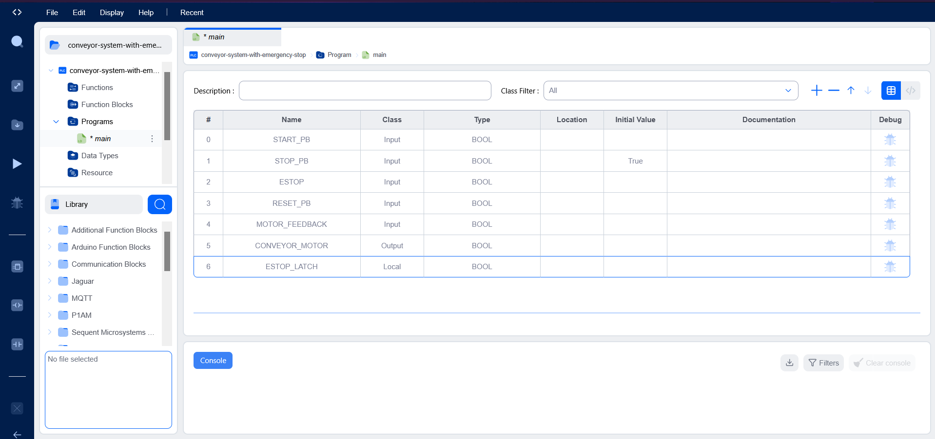
- START_PB — Normally Open (NO) momentary pushbutton contact; initiates motor start command when closed
- STOP_PB — Normally Closed (NC) contact in series with motor rung; de-energizes output coil on activation, consistent with fail-safe wiring practice
- ESTOP — Highest-priority Emergency Stop input; sets the
ESTOP_LATCHinternal memory bit on activation and forces immediate motor output de-energization - RESET_PB — Manually operated normally open reset contact; the sole mechanism for clearing the
ESTOP_LATCHfault state and restoring start capability - CONVEYOR_MOTOR — Discrete Boolean output coil driving the motor contactor; energized only when all safety and operational conditions are simultaneously satisfied
- ESTOP_LATCH — Internal non-retentive Boolean memory bit implementing the fault latch; set by E-stop activation, cleared exclusively by
RESET_PBassertion
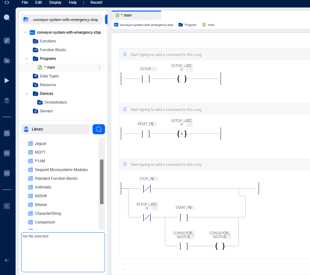
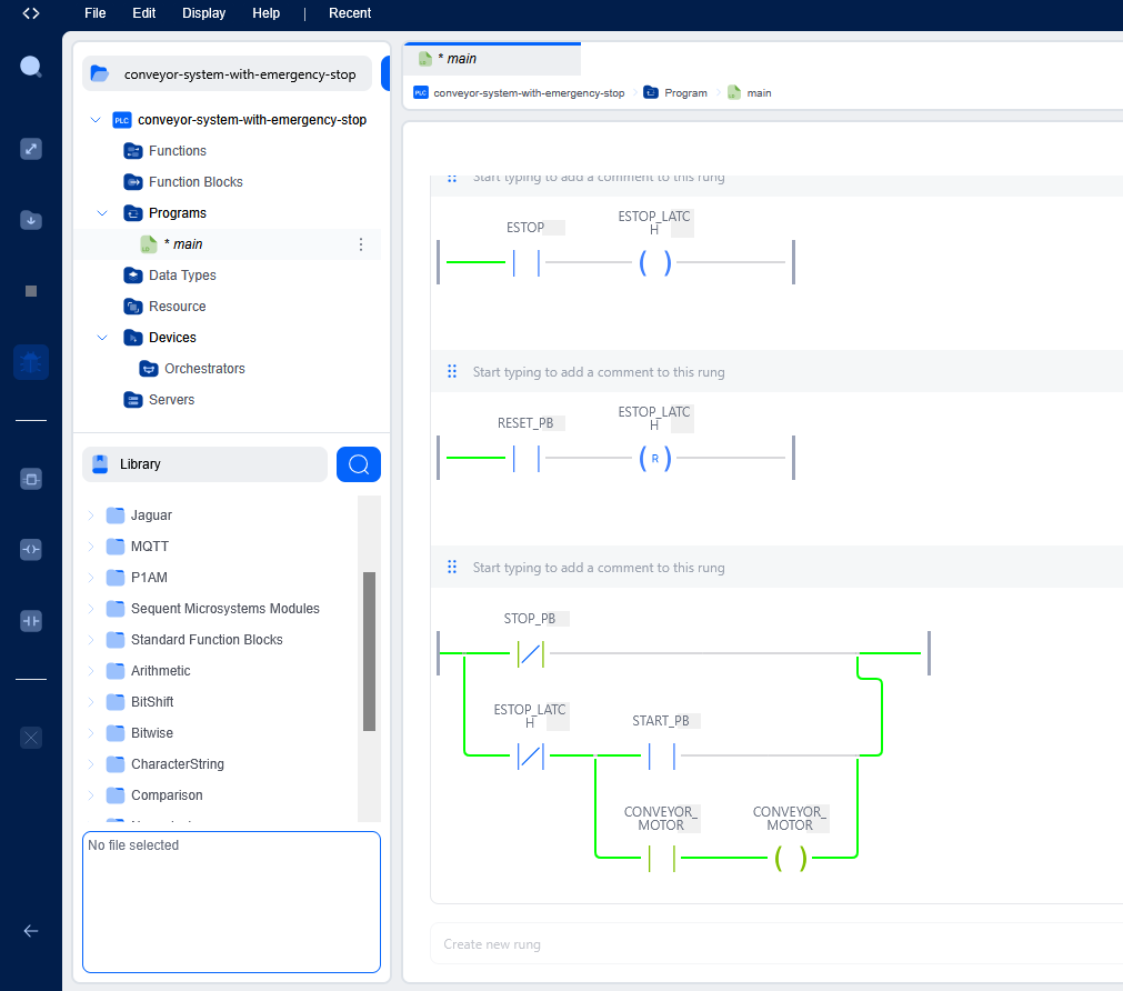
The Emergency Stop fault latch was implemented as an internal coil that is set
on the rising edge of ESTOP and held in the energized state regardless
of the E-stop input returning to its deasserted state. A normally closed contact
driven by ESTOP_LATCH is placed in series with the motor output rung,
ensuring the conveyor remains inhibited until the operator explicitly asserts
RESET_PB to unlatch the fault condition. The seal-in holding circuit
on the motor rung maintains the run state across Start button release under normal
operation, while remaining subordinate to both the Stop and E-stop paths in the
rung evaluation order.
Project Screenshots
Variables Used
VAR_INPUT
    START_PB        : BOOL := FALSE;
    STOP_PB         : BOOL := TRUE;
    ESTOP           : BOOL := FALSE;
    RESET_PB        : BOOL := FALSE;
    MOTOR_FEEDBACK  : BOOL := FALSE;
END_VAR

VAR_OUTPUT
    CONVEYOR_MOTOR  : BOOL := FALSE;
END_VAR

VAR
    ESTOP_LATCH     : BOOL := FALSE;
END_VAR
Testing & Debugging
System verification was conducted using the OpenPLC online simulator with manual input forcing to drive the system through all defined operating states and validate correct rung evaluation, latch behavior, and output response under both normal and fault conditions.
- Assertion of
START_PBenergizedCONVEYOR_MOTORoutput coil and confirmed correct seal-in rung activation via the parallel holding contact - Release of
START_PBwith seal-in active verified that the motor output remained energized across scan cycles without requiring continued button depression - Assertion of
STOP_PB(NC contact opened) confirmed immediate motor de-energization and correct seal-in circuit interruption under normal stop conditions - Forcing
ESTOPTRUE confirmed immediate motor output de-energization and correctESTOP_LATCHbit set within the same scan cycle - Releasing
ESTOPwhileESTOP_LATCHremained set verified that the motor output stayed inhibited and could not be re-energized viaSTART_PB— confirming correct latch persistence - Assertion of
RESET_PBclearedESTOP_LATCHand restored motor start capability, confirming the reset rung evaluates correctly and does not inadvertently re-energize the motor output on reset alone
Challenges Faced
The primary challenge was implementing correct latch persistence behavior:
ensuring that ESTOP_LATCH remained set after the Emergency Stop
input returned to its deasserted state, and that the motor output rung
correctly evaluated the latched condition as an inhibit across all subsequent
scan cycles. Early iterations required careful attention to rung evaluation
order to avoid race conditions between the latch set rung and the motor output
rung within the same scan.
A secondary consideration was correctly distinguishing the behavioral and wiring differences between a standard Stop input (NC contact, fail-safe) and the E-stop path — and understanding why these two mechanisms must remain architecturally separate rather than merged into a single de-energization rung. This distinction is foundational to industrial safety control design and directly informed the latch-based approach used here.
Key Learning Outcomes
- Emergency Stop priority architecture and its distinction from standard operator stop logic in industrial safety systems
- Fault latching using internal memory bits with controlled set/reset paths and persistent state across scan cycles
- Seal-in holding circuit design for maintained motor control without continuous operator input
- Normally Open vs. Normally Closed contact semantics and the safety implications of fail-safe NC wiring on stop and E-stop paths
- Rung evaluation order dependencies and scan-cycle-level logic sequencing in Ladder Diagram programs
- Structured online simulation and input-forcing methodology for systematic PLC program verification
Tools Used
- OpenPLC Editor — open-source IEC 61131-3 PLC development environment
- Autonomy Edge — PLC runtime platform for program deployment and simulation
- Ladder Diagram (LD) — IEC 61131-3 graphical programming language for relay-equivalent control logic
- PLC Simulator / Online Debugger — live variable monitoring and input forcing for program verification