06 / Project Screenshots
Implementation Evidence
Fig. 01
FB_Motor [FB1] — Full Interface with Static Variables Expanded
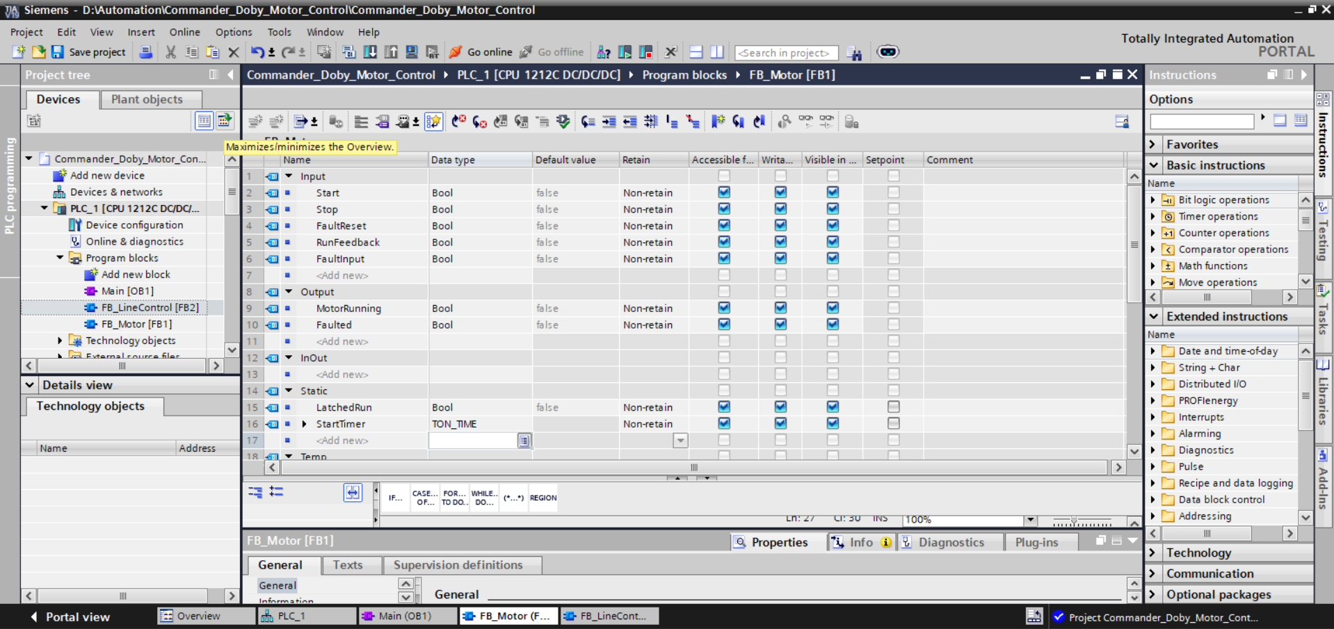
Start, Stop,
FaultReset, RunFeedback, and FaultInput, all typed as Bool with
Non-retain storage. The Output section exposes MotorRunning and Faulted.
The Static section — critical to the DB-backed architecture — shows LatchedRun (Bool)
as the internal state latch, and StartTimer typed as TON_TIME, which is the
run-confirmation watchdog timer whose elapsed time is stored persistently in the instance DB across every
scan cycle. The project tree confirms both FB_LineControl [FB2] and FB_Motor [FB1]
exist under Program Blocks for the CPU 1212C.
Fig. 02
FB_Motor [FB1] — SCL Body: Start/Stop Priority Logic
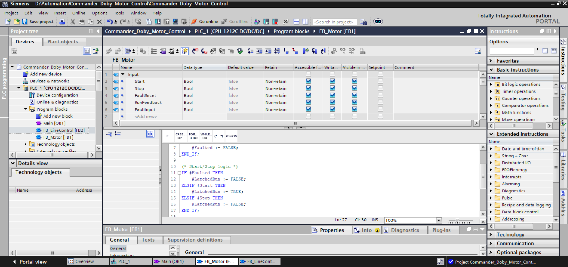
#Faulted when FaultReset is
asserted. Lines 10–17 show the priority-ordered start/stop logic: fault condition evaluates first and
forces #LatchedRun to FALSE, overriding any start command. The ELSIF chain ensures the
start latch only sets when the block is not in a faulted state. This priority model reflects industrial
safety conventions — fault state always wins over run commands on the same scan. The SCL comment
"Start/Stop logic" at line 10 was deliberately placed to assist code review and maintenance.
Fig. 03
FB_Motor [FB1] — First Compile: Warning on Uninitialized Parameter
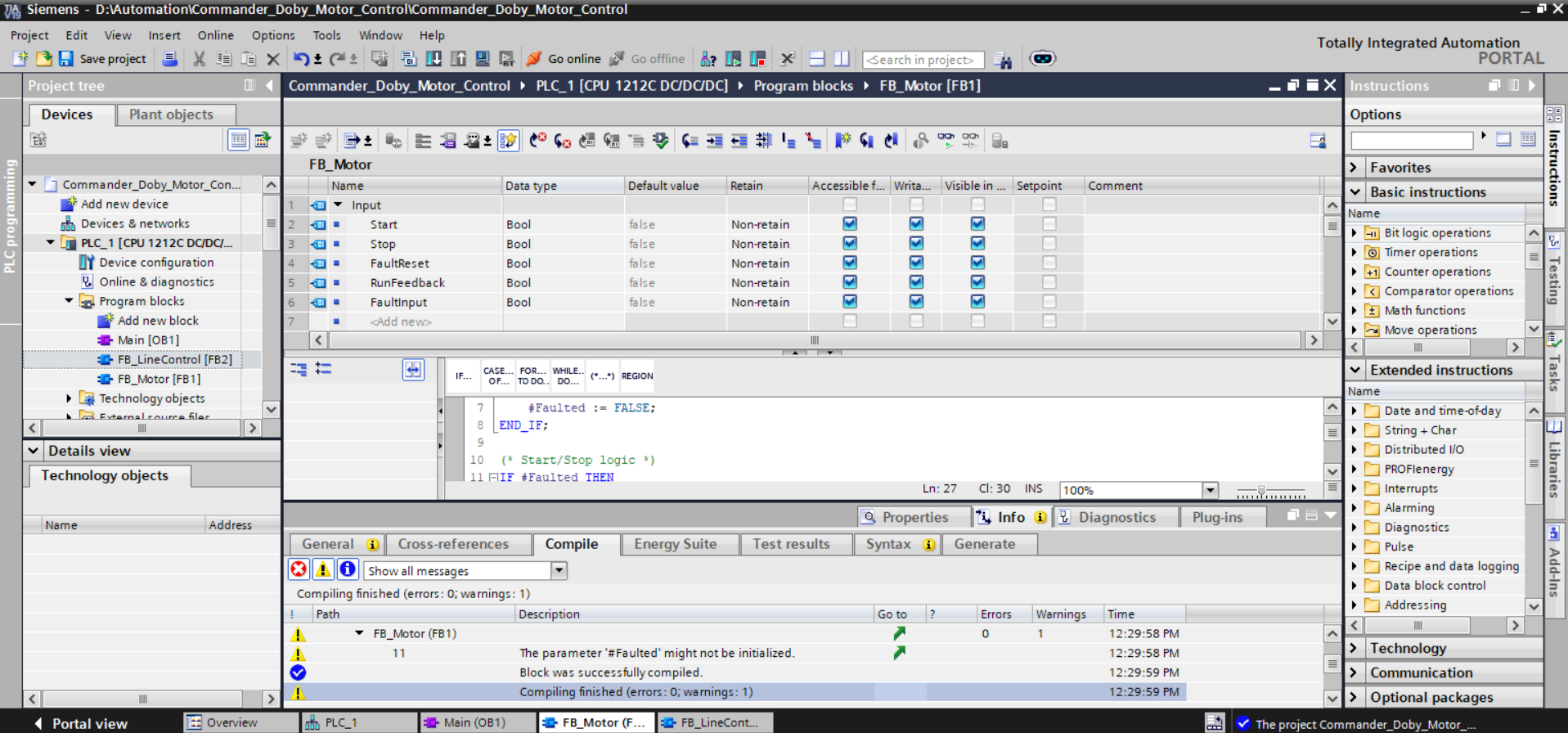
FB_Motor: "The parameter '#Faulted'
might not be initialized." This is a static analysis warning generated because the compiler cannot
guarantee that #Faulted holds a defined value before it is read in the IF condition on line
11 — specifically in the case where FaultReset on line 7 is FALSE and no prior assignment
has occurred. In a real download scenario, the variable defaults to the DB initial value (FALSE), so
runtime behaviour is correct; however, TIA Portal correctly flags this as a code quality issue. The
resolution — adding an explicit initialisation default to the interface table — was applied before final
compilation, as confirmed in Screenshot 6.
Fig. 04
FB_LineControl [FB2] — Interface with Multi-Instance Static Variables
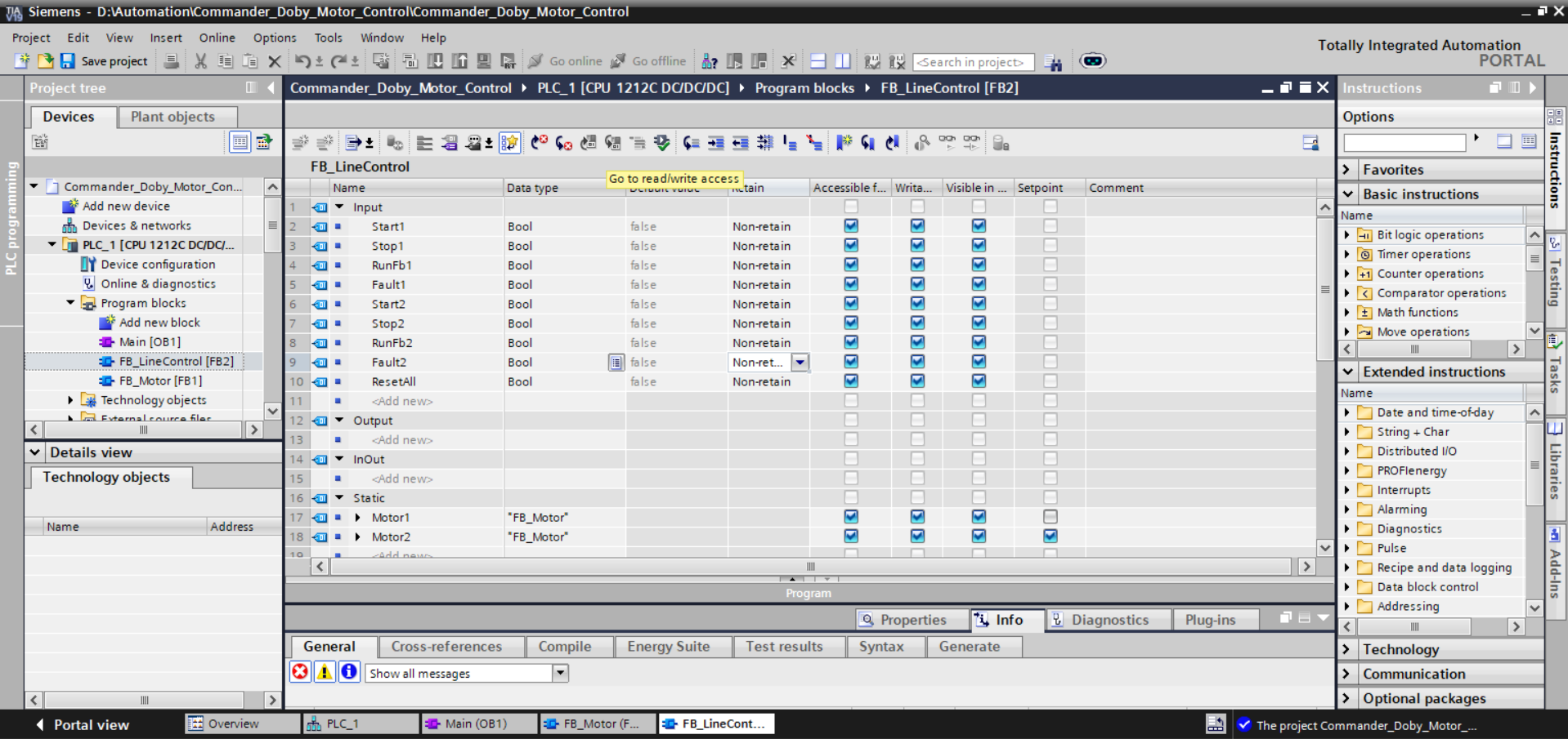
MotorRunning,
Faulted) are accessible from the parent DB directly for SCADA or HMI integration without
requiring additional pass-through outputs on the line controller. The Static section at rows 17–18 is the
architectural core: Motor1 and Motor2 are declared with type
"FB_Motor", instructing TIA Portal to embed the full FB_Motor instance data structure
within DB1 — eliminating the need for two separate instance DBs.
Fig. 05
FB_LineControl [FB2] — SCL Body: Motor Instance Calls
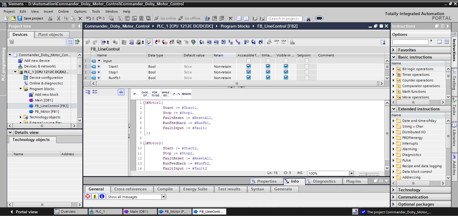
#Motor1 call with named parameter assignment: Start1 → Start,
Stop1 → Stop, ResetAll → FaultReset, RunFb1 → RunFeedback, Fault1 → FaultInput. Lines 9–14 show the
identical structure for #Motor2 using its corresponding input signals. Named parameter
assignment (using :=) is the recommended Siemens style for FB calls — it is order-independent,
self-documenting, and robust to future interface extensions where new optional parameters might be added
without breaking the call site. The symmetry of the two call blocks demonstrates the modularity of the
architecture: identical logic, independent instances, separate state.
Fig. 06
FB_LineControl [FB2] — Clean Compile: 0 Errors, 0 Warnings
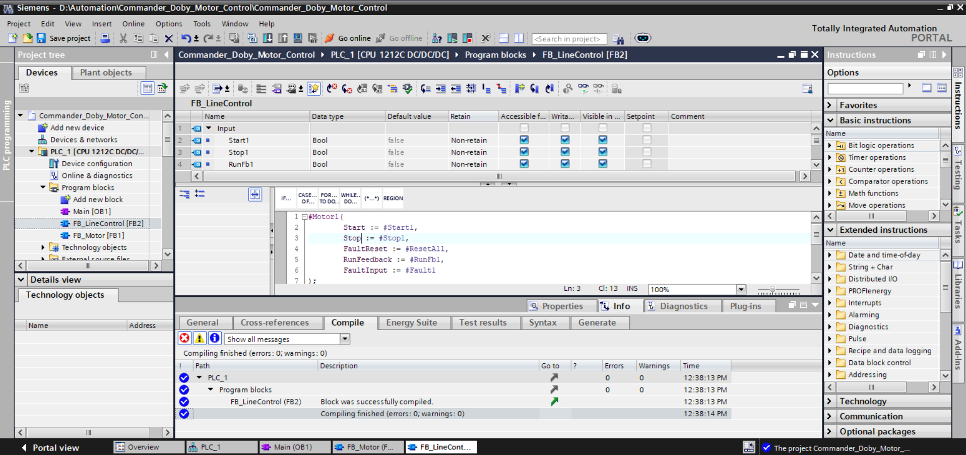
Fig. 07
OB1 — FB_LineControl Call Block in Ladder with Instance DB Assignment
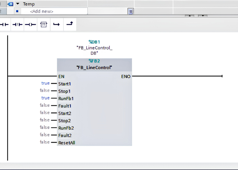
%DB1 / "FB_LineControl_DB" as the assigned instance DB and
%FB2 / "FB_LineControl" as the function block reference. The input connections show
Start1 wired to true, RunFb1 wired to true (simulating a running motor with
feedback present), and all remaining inputs wired to false — a deliberate test configuration
that validates the start and feedback path for Motor1 while Motor2 is held in a stopped state. This
screenshot confirms the complete integration of the FB library into the executable program: the block is
callable, the DB is assigned, and the input interface is fully connected.