Case Study: Water Reclamation Process Control System
A production-grade, multi-tank industrial process control system implemented in CODESYS using IEC 61131-3 Structured Text (ST), encapsulated Function Block architecture, prioritized alarm management, cumulative runtime tracking, and a fully integrated HMI visualization layer
Project Overview
This project implements a fully automated water reclamation and staged transfer control system modeled on real industrial process requirements. The system coordinates fluid flow across three distinct process stages:
- Source Tank — primary water supply reservoir with high/low level sensing
- Process Tank — intermediate treatment and conditioning stage
- Storage Tank — final holding reservoir supplying downstream plant load
Automated transfer between stages is managed by three independently controlled pumps,
each governed by a reusable FB_Pump Function Block that encapsulates
command logic, feedback verification, fault detection, and accumulated runtime tracking.
The control system enforces safe operating envelopes through overflow prevention,
dry-run protection, and hardwired emergency stop handling at the scan-cycle level.
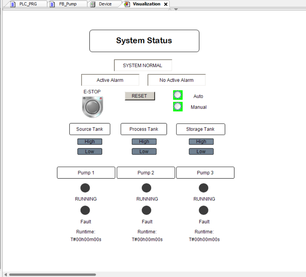
A full operator-facing HMI was implemented using CODESYS Visualization (Visu), providing real-time process status, active alarm display with priority classification, pump runtime indicators, and operator reset controls — all variable-linked directly to the running PLC program.
Problem
The control system was required to autonomously manage a staged fluid transfer process while enforcing safe operational limits across all process conditions. Specific functional requirements included:
- Automatic demand-driven transfer from Source Tank to Process Tank on low-level detection
- Staged transfer from Process Tank to Storage Tank upon high-level threshold satisfaction
- Downstream plant load supply from Storage Tank subject to demand signal and level conditions
- Real-time pump fault detection via feedback signal monitoring with configurable delay tolerances
- Dry-run protection to prevent pump damage under low-suction-head conditions
- Hardwired Emergency Stop with immediate, unconditional de-energization of all pump outputs
- Cumulative runtime accumulation per pump to support preventive maintenance scheduling
- Latched alarm states with operator-initiated reset capability and prioritized alarm reporting
- Live HMI providing process transparency, fault visibility, and operational control actions
Solution
- FB_Pump — encapsulated, reusable Function Block instantiated for all three pumps, exposing standardized I/O interfaces for command, feedback, fault, and runtime outputs
- Auto / Manual Mode — operator-selectable operating modes with Auto enforcing level-driven logic and Manual enabling direct pump command override
- Emergency Stop Override — scan-cycle-level forced de-energization of all pump command outputs, bypassing all conditional logic
- Overflow Detection — high-level sensor monitoring across all tanks with latched fault generation and pump inhibit logic
- Dry Run Protection — low-level sensor interlocks that inhibit pump start commands when suction-head conditions are insufficient
- Pump Fault Detection — feedback-versus-command comparison with configurable timer tolerance to detect start failures and unexpected stop conditions
- Cumulative Runtime Tracking —
TIME-typed accumulators per pump instance, incremented on a per-scan basis while feedback is active - Service Due Alerts — threshold-based runtime comparisons generating maintenance advisory alarms for each pump independently
- System Status Reporting — dynamic
STRING-typed status variable reflecting current operational state for HMI display - Active Alarm String — prioritized alarm concatenation providing a single highest-priority active fault descriptor for operator display
- Full HMI Visualization — CODESYS Visu implementation with live variable binding, color-coded pump state indicators, alarm panels, and operator reset controls
IEC 61131-3 Structured Text was selected as the implementation language due to the multi-instance Function Block architecture, conditional alarm prioritization logic, and runtime accumulation requirements — all of which are significantly more maintainable, testable, and scalable in ST than equivalent Ladder Logic implementations. The modular FB design ensures that any of the three pump instances can be independently diagnosed, modified, or extended without impacting the broader program structure.
Project Screenshots
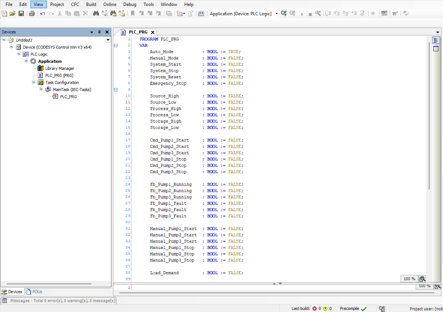
Variables Used
PROGRAM PLC_PRG

VAR
    Auto_Mode            : BOOL := TRUE;
    Manual_Mode          : BOOL := FALSE;
    System_Reset         : BOOL := FALSE;
    Emergency_Stop       : BOOL := FALSE;

    Source_High          : BOOL;
    Source_Low           : BOOL;
    Process_High         : BOOL;
    Process_Low          : BOOL;
    Storage_High         : BOOL;
    Storage_Low          : BOOL;

    Cmd_Pump1_Start      : BOOL;
    Cmd_Pump2_Start      : BOOL;
    Cmd_Pump3_Start      : BOOL;

    Fb_Pump1_Running     : BOOL;
    Fb_Pump2_Running     : BOOL;
    Fb_Pump3_Running     : BOOL;

    Alarm_Overflow       : BOOL;
    Alarm_DryRun         : BOOL;
    Alarm_PumpFault      : BOOL;
    Alarm_HighPriority   : BOOL;

    Pump1_Runtime        : TIME;
    Pump2_Runtime        : TIME;
    Pump3_Runtime        : TIME;

    System_Status        : STRING(50);
    Current_Active_Alarm : STRING(100);
END_VAR
Core Structured Text Logic
(* Fill Process Tank *)
IF Process_Low AND NOT Process_High THEN
    Cmd_Pump1_Start := TRUE;
ELSE
    Cmd_Pump1_Stop := TRUE;
END_IF;

(* Transfer Process → Storage *)
IF Process_High AND NOT Storage_High THEN
    Cmd_Pump2_Start := TRUE;
ELSE
    Cmd_Pump2_Stop := TRUE;
END_IF;

(* Supply Load from Storage *)
IF Storage_High AND Load_Demand THEN
    Cmd_Pump3_Start := TRUE;
ELSE
    Cmd_Pump3_Stop := TRUE;
END_IF;

(* Emergency Stop Override *)
IF Emergency_Stop THEN
    Cmd_Pump1_Start := FALSE;
    Cmd_Pump2_Start := FALSE;
    Cmd_Pump3_Start := FALSE;
END_IF;
Testing & Debugging
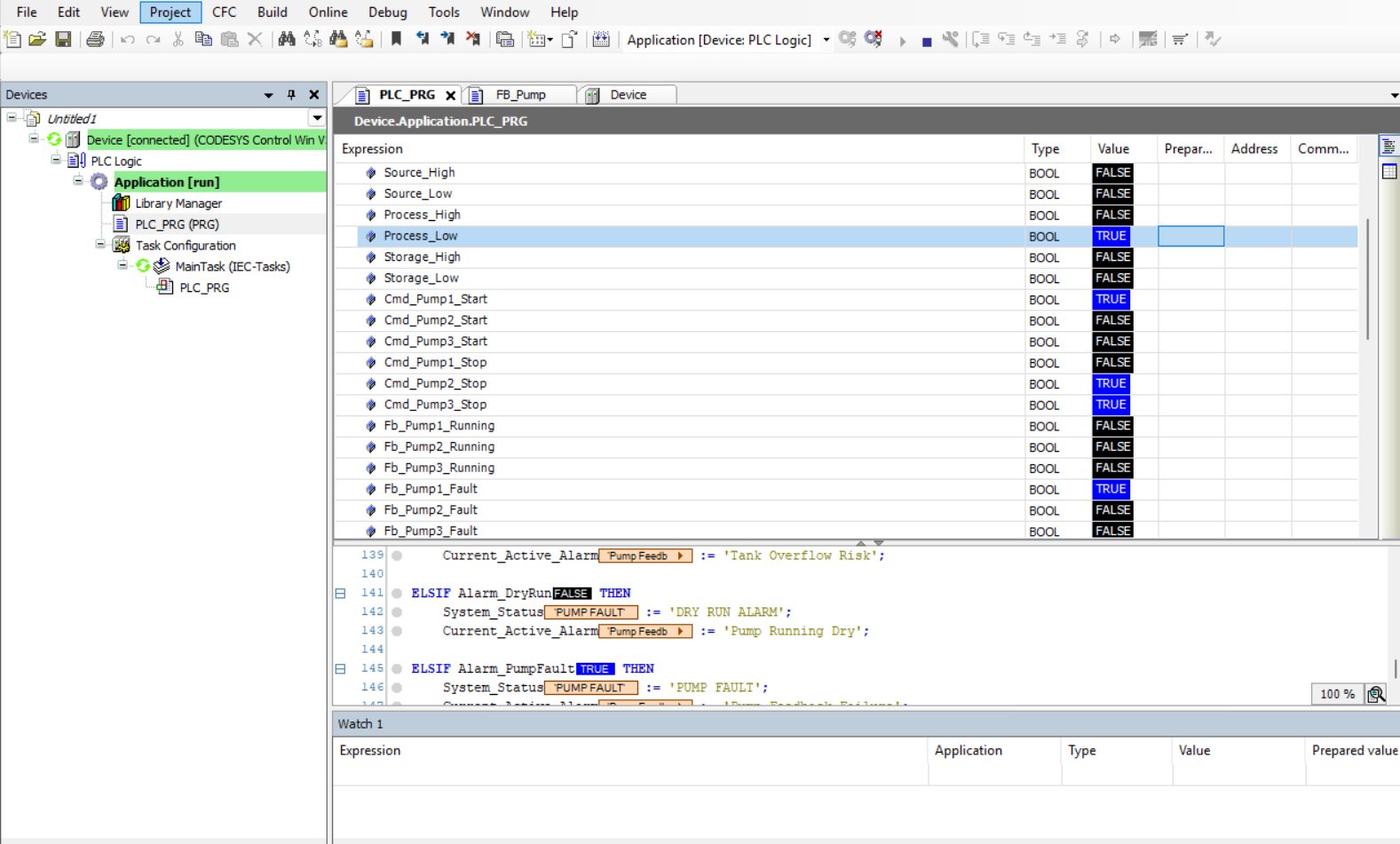
System verification was conducted entirely within the CODESYS online simulation environment using live variable forcing to inject controlled input states and validate deterministic output behavior across all defined operating scenarios and fault conditions.
- Assertion of
Process_Lowcorrectly triggered Pump 1 auto-start with confirmed feedback acknowledgment - Simultaneous
Storage_HighandLoad_Demandasserted to verify Pump 3 supply mode activation and interlock sequencing Emergency_Stopforced TRUE mid-cycle to validate immediate, unconditional de-energization of all pump command outputs within the same scan- Feedback signal withheld post-command to trigger Pump Fault alarm latching and verify alarm string population
- Dry-run protection interlocks verified by asserting low-level conditions on suction-side tanks prior to pump command issuance
- Latched fault states confirmed to persist across scan cycles and clear correctly upon valid
System_Resetassertion - HMI visualization elements verified for live data binding accuracy — pump state indicators, alarm panels, and runtime counters all confirmed to reflect PLC variable state in real time
Challenges Faced
The primary engineering challenge was designing a reusable FB_Pump
Function Block architecture that could be instantiated across three independent
pump contexts while maintaining predictable, non-interfering alarm and fault behavior.
Ensuring that latched alarm states in one instance did not propagate incorrectly
through shared status variables required careful scoping of internal FB state and
explicit output mapping at the program level.
Debugging multi-stage conditional logic required tracing the full signal chain — from raw sensor input through command evaluation, feedback comparison, timer expiry, and alarm latch — rather than relying on final output observation alone. This reinforced disciplined use of intermediate status variables and structured test case design to isolate individual logic branches during verification.
Implementing the HMI required precise variable binding between Visu elements and PLC program variables, with particular attention to ensuring that pump run/fault/alarm state indicators accurately reflected the underlying Boolean logic states rather than command outputs alone — distinguishing between commanded and confirmed running states was essential for correct operator feedback.
Key Learning Outcomes
- IEC 61131-3 compliant Function Block design with encapsulated state, parameterized I/O, and multi-instance reuse
- Industrial alarm management including fault latching, priority classification, and operator reset workflows
- Multi-stage process coordination with interlocked pump sequencing and level-driven control logic
- Structured Text programming discipline within the CODESYS V3.5 development environment
- CODESYS Visualization (Visu) implementation with live PLC variable binding and dynamic element control
- Cumulative runtime accumulation and threshold-based maintenance advisory generation
- Safety-critical Emergency Stop design ensuring unconditional output de-energization at the scan-cycle level
Tools Used
- CODESYS V3.5 — IEC 61131-3 PLC development environment
- CODESYS Control Win — software-based PLC runtime for simulation and online testing
- Structured Text (ST) — IEC 61131-3 high-level textual programming language
- Function Blocks (FB) — encapsulated, reusable logic units with persistent internal state
- CODESYS Visualization (Visu) — integrated HMI development and runtime display layer
- Online Monitoring & Force Debugging — live variable observation and controlled input injection for system verification