Case Study: Reusable Motor Controller Function Block
IEC 61131-3 Ladder Logic implementation of a scalable, fault-aware motor control Function Block in CODESYS — featuring feedback validation, TON timer-based fault detection, latched safe-state output, and multi-instance deployment
Project Overview
This project demonstrates the design and implementation of a reusable FB_Motor Function Block
in CODESYS V3, programmed in IEC 61131-3 Ladder Logic (LD). Rather than duplicating start/stop logic
across individual Program Organisation Units (POUs) for each motor asset, the controller was encapsulated
as a self-contained Function Block with a defined VAR_INPUT/VAR_OUTPUT interface — allowing it to be
instantiated multiple times within PLC_PRG with independent internal state per instance.
The design objective was to move beyond basic coil-driven motor output and implement an industrial-grade controller with mode-gated start authority, run-confirm feedback validation, timer-based fault detection, latching fault output, and automated safe-state shutdown — all within a single reusable and maintainable Function Block structure consistent with real production PLC architectures.
Problem
In industrial automation, a PLC commanding a motor output does not guarantee that the motor has physically started. Drive faults, contactor failures, wiring faults, or mechanical issues can all result in a motor that is commanded ON but not actually running. Without feedback validation and a watchdog timer, the control system has no means to detect this discrepancy, leaving the process in an undefined state with no fault indication and no automatic recovery path.
The requirement was to implement a controller that detects feedback absence within a defined time window following a start command, latches a fault output upon detection, forces the motor output to a safe de-energised state, and prevents restart until an operator-issued reset is received — mirroring the behaviour expected of a certified motor management relay or intelligent motor control centre (MCC) in a production environment.
Solution
- Start (VAR_INPUT) — Rising-edge start command; evaluated only when
Auto_Modeis active and no fault is latched - Stop (VAR_INPUT) — Immediate de-energise command; unconditionally resets the
Runninglatch - Reset (VAR_INPUT) — Operator fault acknowledgement; clears the
Faultedlatch to re-enable start authority - Auto_Mode (VAR_INPUT) — Mode gate; prevents start command from being accepted in manual or maintenance modes
- Feedback (VAR_INPUT) — Run-confirm signal from motor starter, drive ready output, or auxiliary contact; used to validate motor running state
- Running (VAR_OUTPUT) — Latched output; SET on valid start, RESET on stop command or fault condition
- Faulted (VAR_OUTPUT) — Latched fault output; SET when
Fault_Timer.Qfires; forcesRunningRESET and inhibits restart until cleared - Fault_Timer (TON) — On-delay timer; begins counting when
Runningis asserted butFeedbackis absent; fires fault output after 3-second watchdog interval
Set and Reset coils were used throughout to implement stable SR latching behaviour, ensuring that
Running and Faulted states persist correctly across scan cycles without
requiring continuous coil energisation. The TON timer acts as a watchdog: its input
is conditioned on Running AND NOT Feedback, so the timer resets immediately if feedback
is confirmed within the 3-second window. If feedback is not received before PT elapses,
Fault_Timer.Q fires, latching Faulted and triggering an unconditional
RESET of Running — placing the motor in a safe de-energised state pending operator
acknowledgement.
Project Screenshots
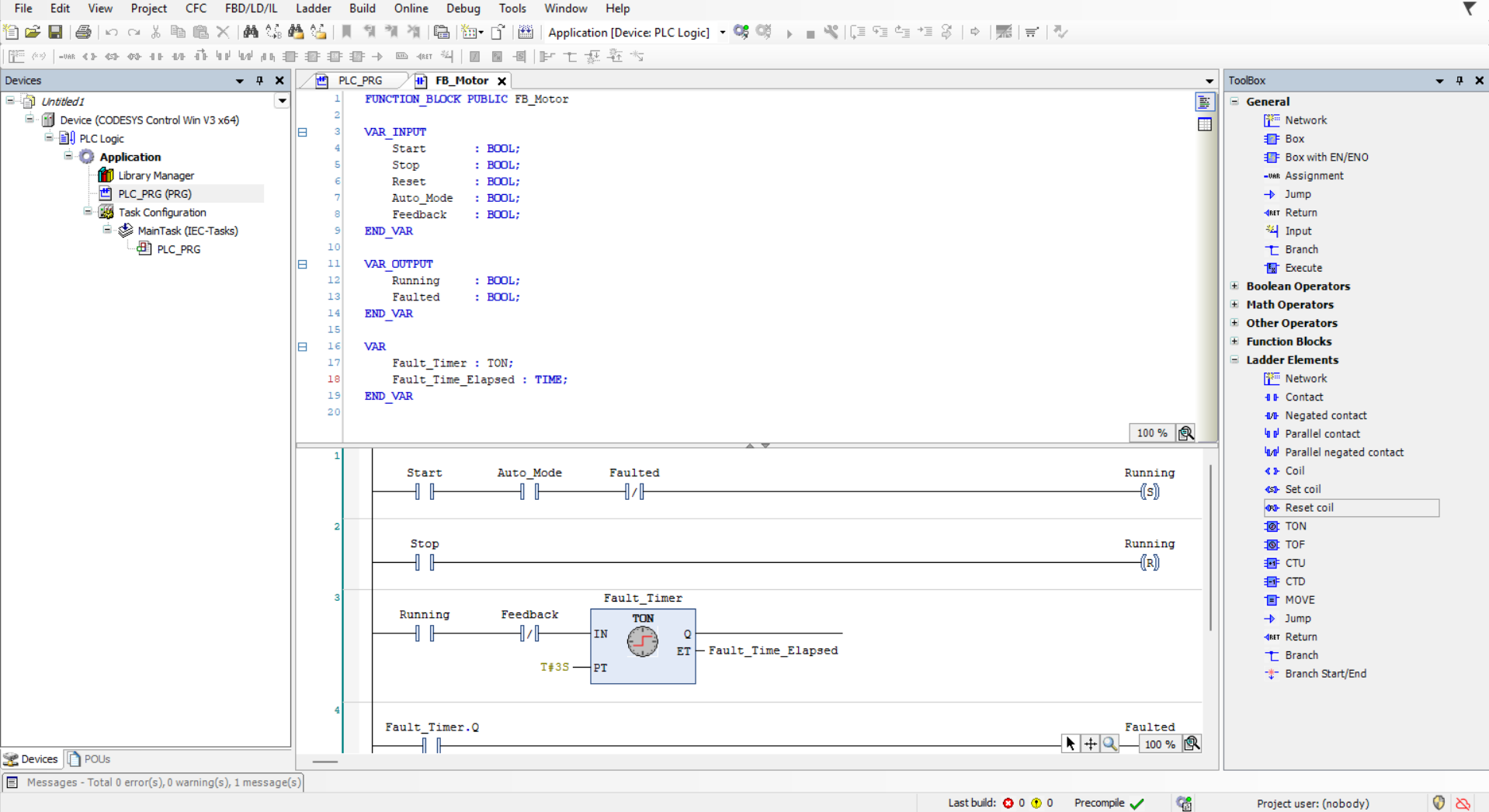
FB_Motor — showing SR latch rungs, mode gate, and fault inhibit conditions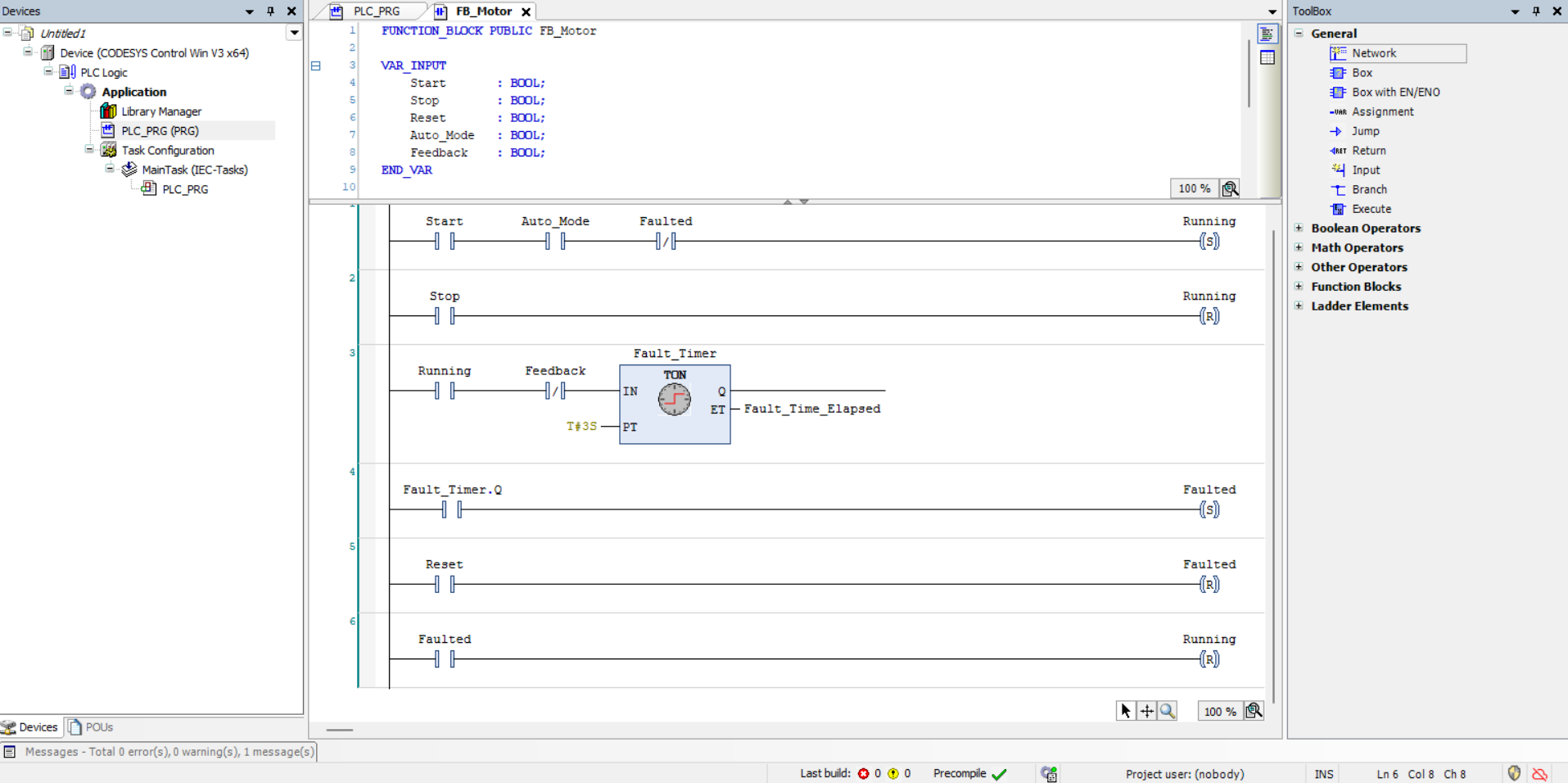
Running asserted with Feedback absent; Fault_Timer.Q output driving Faulted SET coil and Running RESET coil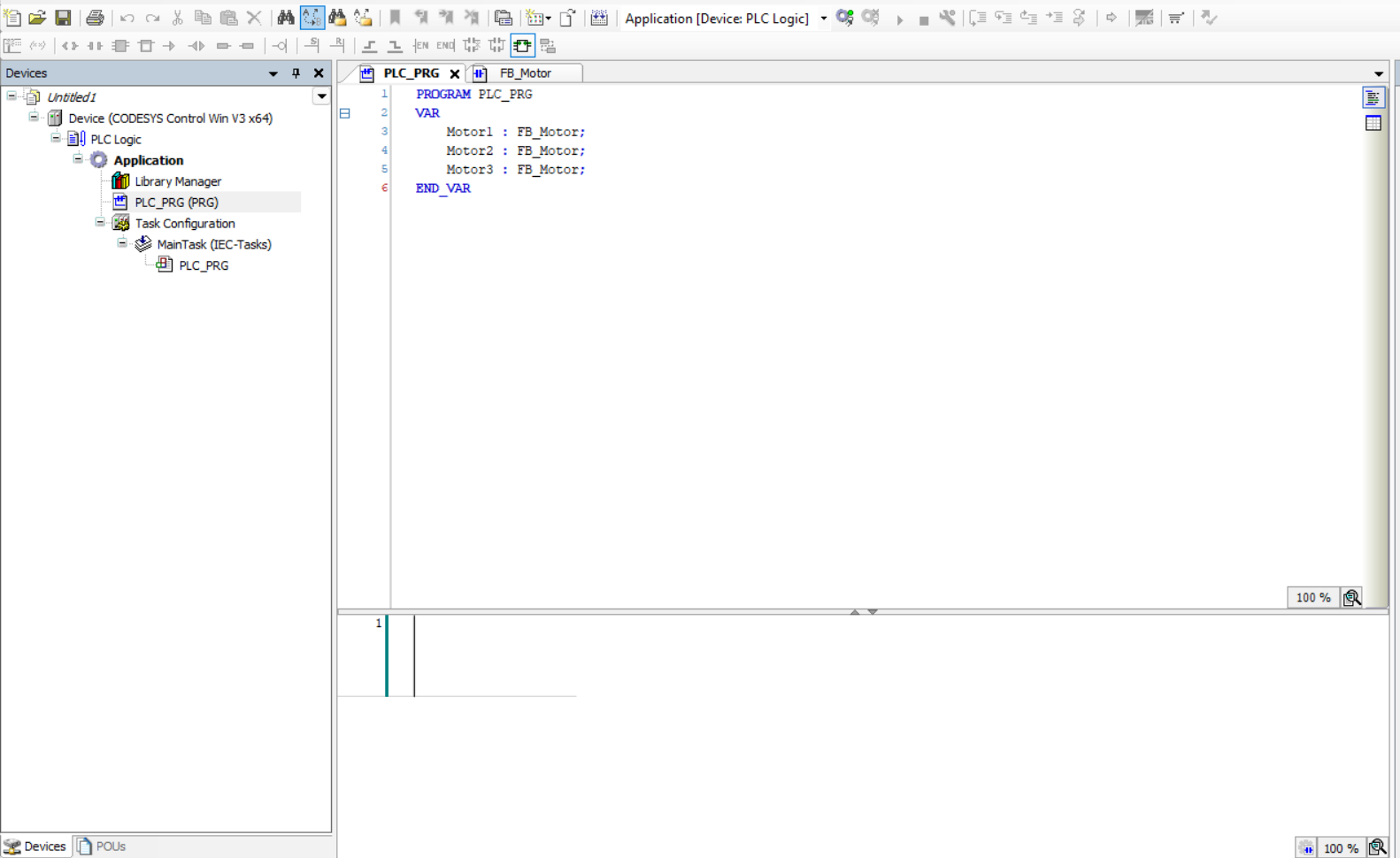
PLC_PRG instantiating Motor1, Motor2, and Motor3 as independent FB_Motor instances — each maintaining isolated internal stateVariables Used
FUNCTION_BLOCK FB_Motor

VAR_INPUT
    Start       : BOOL;   (* Start command — accepted only when Auto_Mode TRUE and Faulted FALSE *)
    Stop        : BOOL;   (* Stop command — unconditionally resets Running latch *)
    Reset       : BOOL;   (* Operator fault acknowledgement — clears Faulted latch *)
    Auto_Mode   : BOOL;   (* Mode gate — inhibits Start in manual or maintenance mode *)
    Feedback    : BOOL;   (* Run-confirm input from motor starter auxiliary contact or drive ready signal *)
END_VAR

VAR_OUTPUT
    Running     : BOOL;   (* Latched run output — SET on valid start, RESET on Stop or Fault *)
    Faulted     : BOOL;   (* Latched fault output — SET on watchdog timeout, cleared by Reset *)
END_VAR

VAR
    Fault_Timer         : TON;   (* IEC on-delay timer — watchdog for feedback confirmation *)
    Fault_Time_Elapsed  : TIME;  (* Elapsed time reference for monitoring and diagnostics *)
END_VAR
Core Ladder Logic
Rung 1 — Start Authority and Running Latch:
Start AND Auto_Mode AND NOT Faulted
→ SET Running
(* Mode gate and fault inhibit evaluated before start command is accepted *)

Rung 2 — Stop Command:
Stop
→ RESET Running
(* Unconditional stop; no interlock conditions *)

Rung 3 — Watchdog Timer Enable:
Running AND NOT Feedback
→ TON Fault_Timer (PT := T#3s)
(* Timer resets immediately if Feedback confirmed; fires fault after 3s absence *)

Rung 4 — Fault Latch on Timer Expiry:
Fault_Timer.Q
→ SET Faulted

Rung 5 — Fault Reset:
Reset
→ RESET Faulted
(* Operator acknowledgement clears latch; re-enables start authority *)

Rung 6 — Safe-State Shutdown on Fault:
Faulted
→ RESET Running
(* Guarantees motor is de-energised whenever fault is latched *)
Testing & Debugging
Functional verification was performed using CODESYS online monitoring with forced and written variable injection to exercise every rung condition and confirm correct SR latch behaviour, timer operation, and fault sequencing across all three instantiated motor objects.
Startforced TRUE withAuto_ModeFALSE — confirmed start command correctly inhibited;Runningremained de-assertedStartandAuto_Modeboth forced TRUE — confirmedRunningSET latch asserted and persisted afterStartreleasedFeedbackwithheld after start — confirmedFault_Timerbegan accumulating; elapsed time monitored online- TON timer allowed to reach
PT = T#3s— confirmedFault_Timer.Qfired,FaultedSET latch activated, andRunningRESET coil executed within same scan Resetforced TRUE whileFaultedactive — confirmed fault latch cleared and start authority restored- All three
FB_Motorinstances (Motor1, Motor2, Motor3) tested independently — confirmed instance isolation with no cross-contamination of internal state
Challenges Faced
The primary architectural challenge was transitioning from flat, output-driven Ladder Logic into a proper IEC 61131-3 Function Block design pattern. This required understanding how CODESYS manages separate POUs, how Function Block instances encapsulate their own internal variable state independently of other instances, and how VAR_INPUT and VAR_OUTPUT interfaces define the contract between the FB and the calling program — concepts directly analogous to object-oriented encapsulation in software engineering.
A specific challenge arose in correctly sequencing the fault latch and running reset across scan cycles. Because CODESYS executes rungs sequentially within a single scan, the order of Rung 4 (SET Faulted) and Rung 6 (RESET Running on Faulted) was critical to ensure that the safe-state shutdown executed within the same scan as the fault latch — eliminating any one-cycle window during which the motor output could remain asserted after a fault event.
Key Learning Outcomes
- Designing and implementing encapsulated IEC 61131-3 Function Blocks with typed VAR_INPUT/VAR_OUTPUT interfaces
- Applying reusable PLC design patterns to eliminate logic duplication across multi-motor plant architectures
- Implementing stable SR latching behaviour in Ladder Logic using Set and Reset coils
- Using TON on-delay timers as watchdog elements for run-confirm feedback validation
- Structuring scan-cycle-aware rung ordering to ensure atomic fault detection and safe-state shutdown
- Verifying multi-instance FB behaviour through structured online force testing in CODESYS
Tools Used
- CODESYS V3.5 SP22 — IEC 61131-3 compliant PLC development environment
- CODESYS Control Win — software-based PLC runtime for local simulation and online testing
- Ladder Logic (LD) — IEC 61131-3 graphical programming language
- TON Function Block — IEC standard on-delay timer used as watchdog element
- Online Monitoring, Force, and Write Tools — real-time variable observation and controlled signal injection for structured functional verification