Case Study: Battery Storage Charge/Discharge Logic
CODESYS Structured Text (IEC 61131-3) implementation of a Battery Energy Storage System (BESS) featuring deterministic state machine control, fault prioritisation, and hysteresis-based threshold management
Project Overview
This project implements a Battery Energy Storage System (BESS) controller using IEC 61131-3 Structured Text within the CODESYS V3 development environment. The system manages the full operational lifecycle of a battery asset — including charge acceptance, full-charge detection, load-driven discharge, low-voltage protection, and fault-triggered safe shutdown — through a formally structured finite state machine (FSM). The design prioritises deterministic state transitions, safe-state fallback behaviour, and immunity to spurious switching, making it directly applicable to grid-tied renewable energy integration, UPS systems, and microgrid control.
Problem
Industrial battery systems operating at the interface of variable renewable generation and dynamic load demand require control logic that is both responsive and inherently safe. Without structured transition rules, a battery controller is vulnerable to rapid state oscillation (chattering) near voltage thresholds, missing fault detection during active charge or discharge cycles, and unsafe recovery sequences that re-enter operation before electrical conditions are confirmed stable. These failure modes can cause accelerated cell degradation, contactor wear, BMS trips, or — in worst-case scenarios — thermal runaway. The challenge was to implement a controller that enforces strict transition guards, guarantees fault preemption across all states, and provides verifiable, auditable behaviour under all simulated input combinations.
Solution
- IDLE (0) — Default quiescent state; no charge or discharge commands asserted; system awaits a valid trigger condition
- CHARGING (1) — Entered when solar availability is confirmed and
BatteryVoltageis below the upper charge threshold;ChargeCommandis asserted to the power electronics layer - FULL (2) — Voltage has reached or exceeded the defined full-charge setpoint;
ChargeCommandis de-asserted and the system holds until load demand or voltage decay triggers a transition - DISCHARGING (3) —
LoadDemandis active and battery voltage is above the minimum discharge threshold;DischargeCommandis asserted to the inverter stage - EMPTY (4) — Battery voltage has fallen to the low-voltage cutoff threshold;
DischargeCommandis de-asserted to protect cell chemistry and prevent deep discharge damage - FAULT (5) — Entered immediately from any state upon detection of an overvoltage or undervoltage condition outside safe operating limits; all output commands are cleared and the system latches until a manual reset with confirmed safe voltage is received
Hysteresis bands were implemented around the FULL and CHARGING threshold voltages to eliminate boundary oscillation caused by sensor noise or minor voltage ripple. Rather than using a single setpoint, separate enter and exit thresholds enforce a deadband that prevents the state machine from toggling at high frequency. Fault detection logic was structured as a priority-evaluated guard that executes unconditionally before any state-specific transition logic, ensuring that overvoltage and undervoltage events are captured regardless of which operational state is currently active.
Project Screenshots
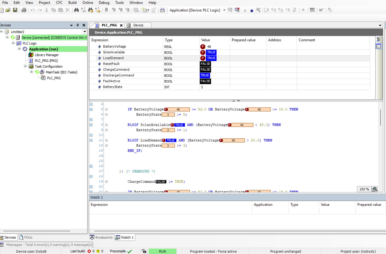
BatteryState = 1; ChargeCommand asserted with solar availability confirmed and voltage below upper threshold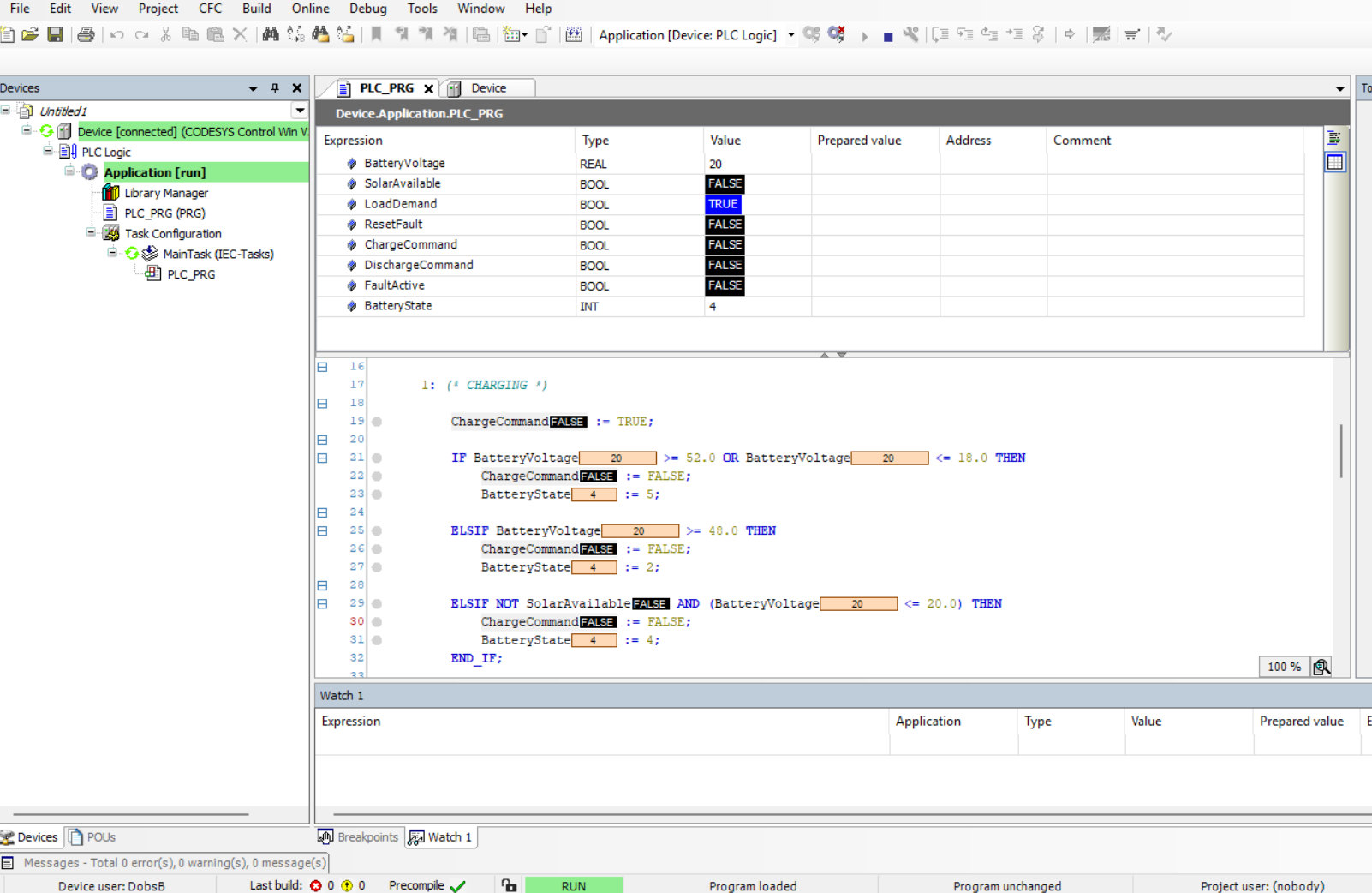
BatteryState = 4; DischargeCommand de-asserted as BatteryVoltage reaches low-voltage cutoff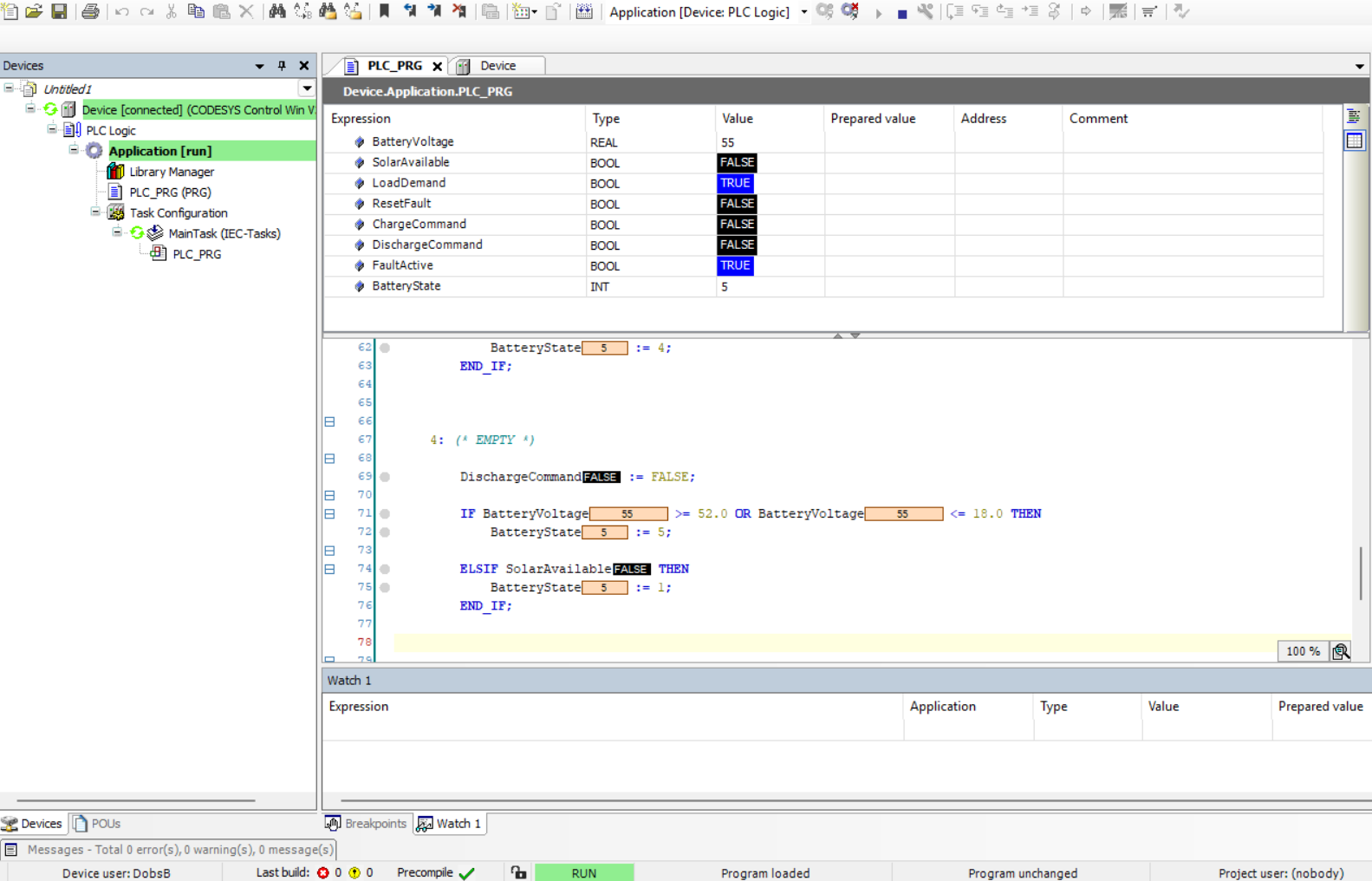
BatteryState = 5; all output commands cleared and FaultActive latched following out-of-range voltage detection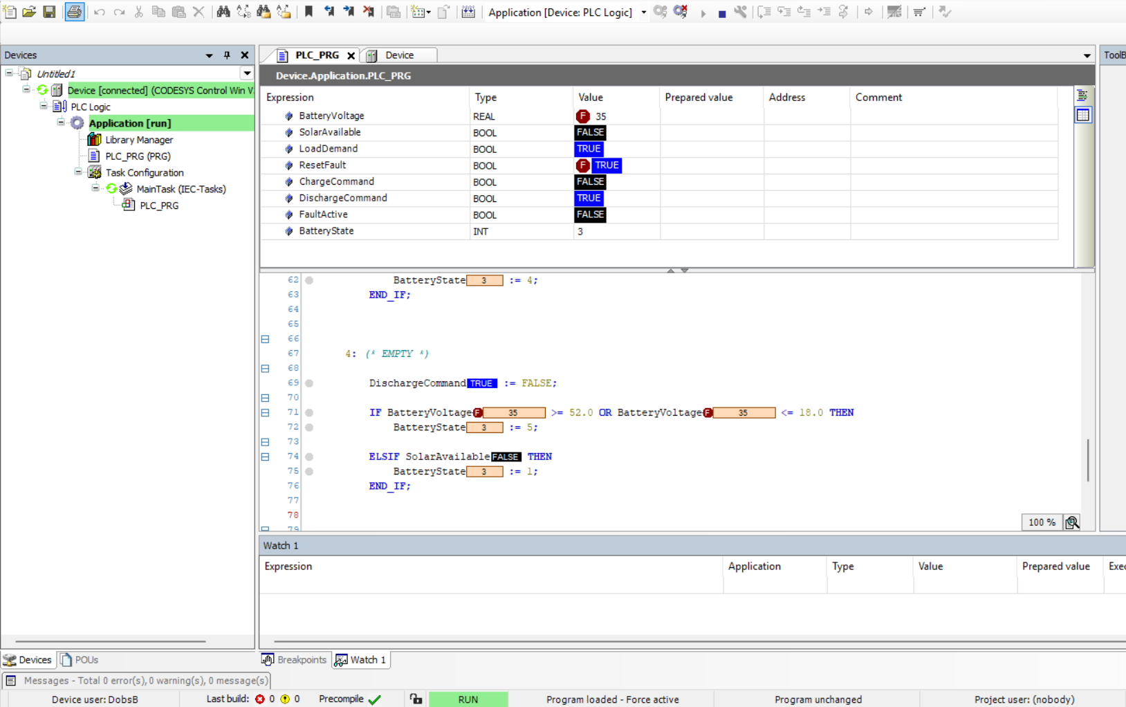
ResetFault accepted only after voltage confirmed within safe operating window; system returns to IDLEVariables Used
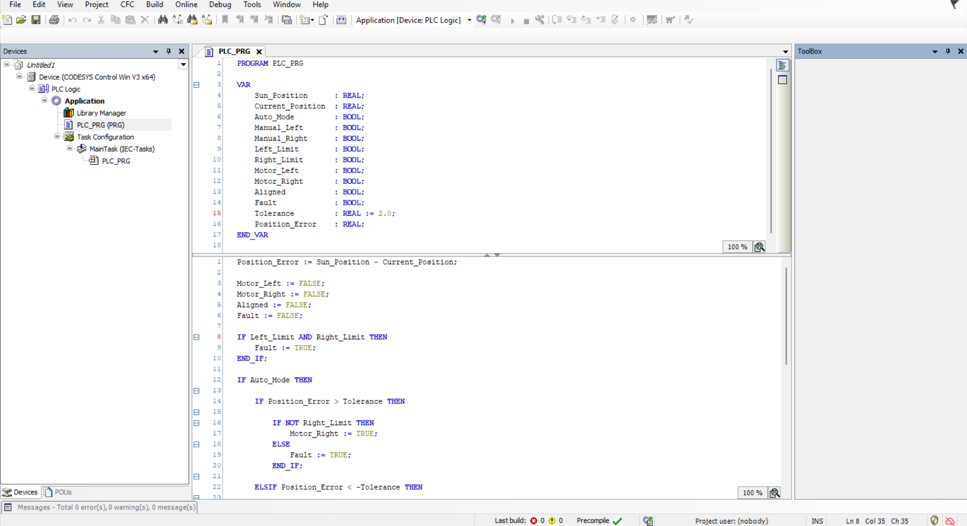
VAR
    BatteryVoltage : REAL := 35.0;   (* Analogue input — battery terminal voltage in volts (REAL for threshold comparison) *)

    SolarAvailable : BOOL := FALSE;  (* Digital input — TRUE when PV generation is present and above minimum yield *)
    LoadDemand     : BOOL := FALSE;  (* Digital input — TRUE when downstream load requires battery discharge *)
    ResetFault     : BOOL := FALSE;  (* Operator reset flag — evaluated only after voltage re-enters safe band *)

    ChargeCommand     : BOOL := FALSE;  (* Output to charge controller / rectifier stage *)
    DischargeCommand  : BOOL := FALSE;  (* Output to inverter / discharge circuit *)
    FaultActive       : BOOL := FALSE;  (* Latching fault flag — cleared only by valid reset sequence *)

    BatteryState : INT := 0;  (* FSM state register: 0=IDLE, 1=CHARGING, 2=FULL, 3=DISCHARGING, 4=EMPTY, 5=FAULT *)
END_VAR
Testing & Debugging
Verification was conducted using CODESYS online monitoring with forced and written variable injection to exercise every defined state transition path. Input conditions were systematically varied to validate correct guard evaluation, confirm that fault preemption fired from all non-FAULT states, and ensure that the reset sequence rejected premature recovery attempts when voltage remained outside the safe band.
- Solar input asserted → IDLE transitions to CHARGING;
ChargeCommandconfirmed active - Voltage incremented past upper threshold → FULL state activated;
ChargeCommandde-asserted and hysteresis band confirmed effective LoadDemandset TRUE → system transitions from FULL to DISCHARGING;DischargeCommandasserted- Voltage decremented to low-voltage cutoff → EMPTY state entered;
DischargeCommandcleared; cell protection confirmed - Voltage forced outside safe limits during CHARGING and DISCHARGING → FAULT state entered immediately from both active states, validating priority guard implementation
ResetFaultasserted with voltage still out-of-range → reset correctly rejected; system remained in FAULT; reset accepted only after voltage restored to safe window
Challenges Faced
The primary engineering challenge was ensuring that fault detection evaluated unconditionally at every scan cycle, regardless of the currently active state. Early iterations placed fault checks only within the IDLE and DISCHARGING branches, leaving CHARGING and EMPTY states without fault preemption coverage — a latent safety gap that would be unacceptable in a production system. This was resolved by restructuring the FSM so that fault guard logic executes as a top-level priority check before any state-specific branch is evaluated, matching the safety architecture expected in industrial PLC design.
A secondary challenge involved understanding the distinction between CODESYS force operations and write operations during online debugging. Forced values override the PLC program's output for the duration of the force, while written values are immediately subject to overwrite by program logic in the next scan — a critical distinction when simulating input signals versus testing output behaviour. Correctly applying this distinction was essential for generating reliable test results and accurately reproducing edge-case transitions.
Key Learning Outcomes
- Authoring production-structured IEC 61131-3 Structured Text for industrial PLC environments
- Designing and implementing finite state machines with formally defined transition guards and priority evaluation
- Applying hysteresis and deadband logic to eliminate threshold oscillation in analogue-triggered state machines
- Structuring fault prioritisation so safety conditions preempt normal operation from any active state
- Handling REAL-typed analogue inputs with upper and lower setpoint comparisons for multi-zone threshold logic
- Conducting structured PLC verification using CODESYS online monitoring, variable forcing, and write-value injection
Tools Used
- CODESYS V3 — IEC 61131-3 compliant PLC development environment
- Structured Text (ST) — IEC 61131-3 high-level PLC programming language
- CODESYS SoftPLC Simulator — software-based PLC runtime for offline and online testing
- Online Monitoring, Force, and Write Tools — real-time variable observation and controlled input injection
- Battery Energy Storage System (BESS) Simulation — modelled renewable energy storage and load scenario