Case Study: WinCC HMI — Batch Mixer Control Panel
A production-grade SIMATIC WinCC Comfort operator interface implemented in Siemens TIA Portal for an S7-1212C DC/DC/DC PLC — covering HMI tag architecture, dynamic process visualisation, discrete and analogue alarm configuration, alarm buffer management, and live runtime validation in SIMATIC WinCC Runtime Advanced
Project Overview
This project delivers a complete operator interface for an industrial batch mixing station, built as a SIMATIC WinCC Comfort HMI panel project within TIA Portal and validated in WinCC Runtime Advanced. The HMI communicates with a PLC_1 [CPU 1212C DC/DC/DC] and exposes real-time process state to the operator through a structured Root Screen: tank visualisation, live numeric readouts for Level, Step, and Temperature, operator command buttons, and a fully configured alarm system surfacing both process anomalies and connection diagnostics.
The architecture separates concerns cleanly: the PLC owns all control logic; the HMI owns all presentation and operator interaction. Tags are declared once in the PLC and exposed via the HMI connection layer — no control logic executes on the panel. This separation is the same pattern used in pharmaceutical, food and beverage, and chemical processing installations worldwide, where a panel failure must never compromise PLC-level process safety.
Problem
A batch mixing process operating under PLC-level GRAPH sequential control required a structured operator interface that could satisfy the following requirements without embedding any control logic on the HMI side:
- Present live process state (tank level, active step, temperature) with sufficient context for an operator to assess process health at a glance
- Provide safe, interlocked operator commands (Start / Stop) mapped to PLC input tags
- Surface process anomalies — specifically high-temperature conditions — through a configurable alarm system with real-time triggering, alarm class assignment, and persistent alarm buffer logging
- Display connection-level diagnostics alongside process alarms so operators can distinguish between process faults and communication failures without leaving the runtime screen
- Compile and deploy without errors across TIA Portal's full HMI tag validation and alarm consistency checks
Solution Architecture
CurrentStep(Int) — PLC tag, read-only on HMI. Sourced from the GRAPH FB'sS_NOoutput; drives the Step IO field and indirectly the level animation positionHighTempWarning(Bool) — PLC tag; alarm trigger for the HIGH TEMP WARNING discrete alarm. Set by the PLC when the temperature analogue input crosses the process safety thresholdMixerTemperature(Int / Real) — PLC tag; drives the Temperature IO field display and the analogue alarm upper-limit checkTankLevel(Int / Real) — PLC tag; drives the Level (%) IO field and the tank fill animation object@DiagnosticsIndicatorTag(SInt) — WinCC-generated internal diagnostics tag; populates the connection-level alarm entries automatically when the HMI connection to the PLC drops or encounters a module configuration mismatch- Start / Stop command tags — Bool PLC tags toggled by the operator buttons; the PLC's OB1 reads these as permissive inputs rather than direct actuator drivers, preserving PLC-side interlock integrity
- Header bar: Siemens logo, panel title ("Batch Mixer Control Panel"), and live date/time field — orients the operator to the active station at all times
- Tank visualisation: Graphical tank object with a dynamic fill element animated against
TankLevel; a circular status indicator (circle graphic object, colour-animated) provides an at-a-glance running / stopped / fault state without requiring the operator to read text - Operator command section: "Start Batch" and "Stop" buttons, each mapped to a discrete PLC Bool tag via a SetBit / ResetBit event action — no HMI-internal script logic required
- Process readout section: Three IO field objects displaying Level (%), Step (Int), and Temperature (numeric) in real time, each bound to the corresponding PLC-connected tag
- Alarm view panel: Alarm buffer display (not current-alarm view) occupying the right half of the screen; columns for Date, Status, Text, and Acknowledge Group — configured to persist alarm history across operator acknowledgement so production engineers can audit fault occurrence timelines
- Discrete alarm — HIGH TEMP WARNING: Trigger tag
HighTempWarning(Bool), bit 0, rising-edge detection. Alarm class: Warning. Text: "HIGH TEMP WARNING – Mixer overheating". Assigned to acknowledge group 0. This alarm fires when the PLC asserts the flag after the temperature analogue input exceeds the configured safety limit - Analogue alarm (threshold-based): Trigger tag
MixerTemperature, upper-limit mode, threshold value 85 (engineering units). Fires independently of the discrete alarm path — provides a second, tag-direct detection channel that does not depend on PLC-side flag logic, increasing alarm coverage redundancy - System / diagnostics alarms: Auto-generated by WinCC from
@DiagnosticsIndicatorTag— surfaces connection drops, operating mode changes, module configuration errors, and user administration events without requiring manual alarm configuration. These are visible in the runtime alarm buffer alongside process alarms, giving operators a unified fault view - Alarm buffer vs current alarm view: The alarm view object is configured in buffer mode rather than current-alarm mode, ensuring that acknowledged and cleared alarms remain visible in the log for post-event review — a requirement in process industries operating under batch record traceability obligations
HMI Tag Map
Complete tag binding table for the Root Screen, mapping each visual element to its data source and access mode.
| HMI Element | Tag / Source | Type | Access | Notes |
|---|---|---|---|---|
| Level (%) IO field | TankLevel |
PLC-connected | Read | Also drives tank fill animation object via movement property |
| Step IO field | CurrentStep |
PLC-connected (Int) | Read | Sourced from GRAPH FB S_NO output |
| Temperature IO field | MixerTemperature |
PLC-connected | Read | Also used as analogue alarm trigger tag (upper limit 85) |
| Start Batch button | Start command Bool | PLC-connected | Write (SetBit) | Event action on MouseClick; no HMI script |
| Stop button | Stop command Bool | PLC-connected | Write (ResetBit) | Event action on MouseClick |
| Status indicator circle | Derived from process state | Animation | Read | Colour animation: green = running, grey = idle |
| HIGH TEMP WARNING alarm | HighTempWarning (Bool, bit 0) |
PLC-connected | Alarm trigger | Discrete alarm, Warning class, acknowledge group 0 |
| Analogue alarm | MixerTemperature |
PLC-connected | Alarm trigger | Upper limit mode, threshold 85 |
| Alarm view panel | @DiagnosticsIndicatorTag + all alarms |
Internal + PLC | Read | Buffer mode; columns: Date, Status, Text, Ack Group |
Project Screenshots
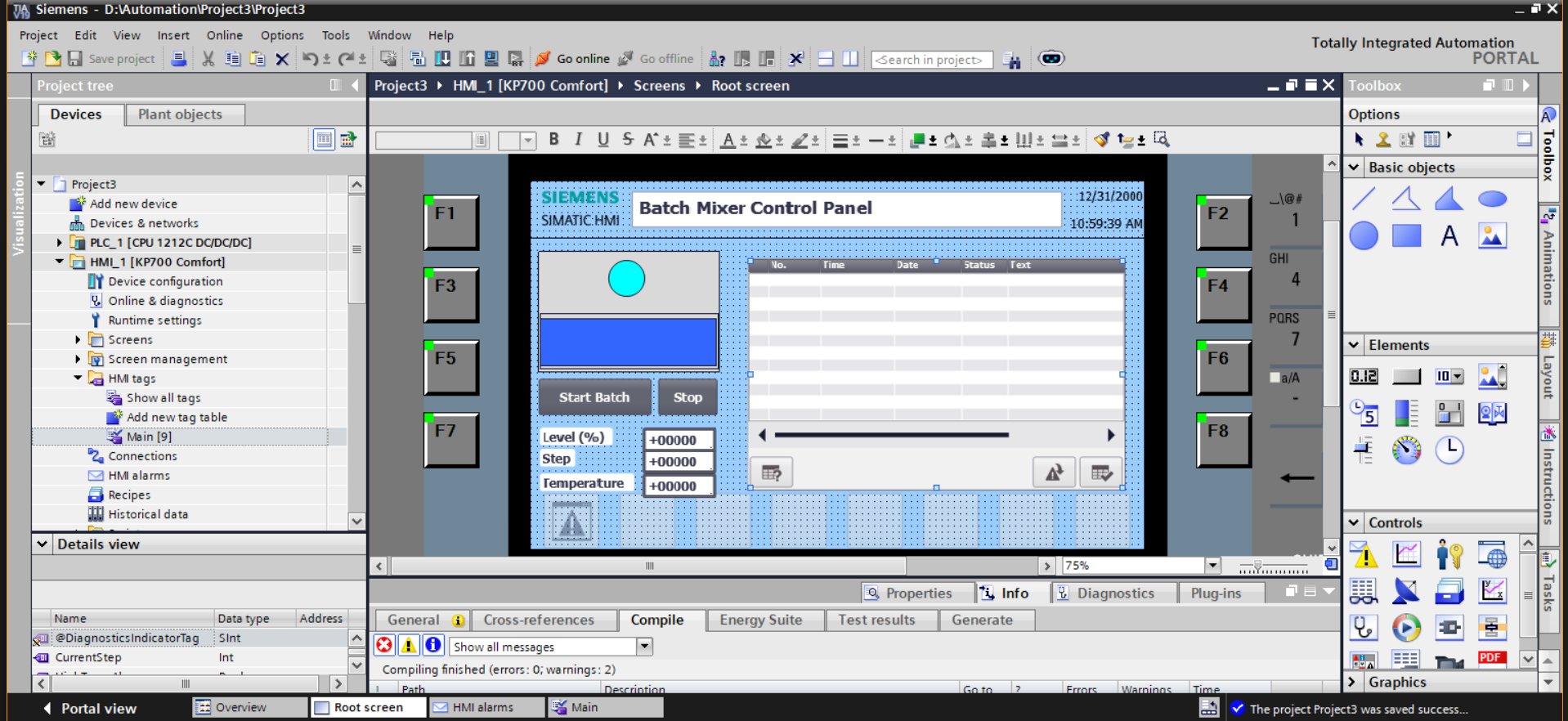
@DiagnosticsIndicatorTag (SInt) and CurrentStep (Int) bindings. Project tree shows HMI_1 [KP700 Comfort] under PLC_1 [CPU 1212C DC/DC/DC]. Compile output: errors 0, warnings 2.
Alarm Configuration — Annotated
# DISCRETE ALARM — HIGH TEMP WARNING
# Trigger tag:  HighTempWarning (Bool, PLC-connected)
# Trigger bit:  0
# Detection:    Rising edge (0 → 1)
# Alarm class:  Warning
# Ack group:    0
# Text:         "HIGH TEMP WARNING – Mixer overheating"
# Appears in:   Alarm buffer (persistent after acknowledgement)
# Set by PLC when MixerTemperature analogue input > safety limit
# Decouples HMI alarm display from analogue threshold arithmetic —
# the PLC evaluates the condition; the HMI only reads the Bool flag.

# ANALOGUE ALARM — TEMPERATURE UPPER LIMIT
# Trigger tag:  MixerTemperature (Int/Real, PLC-connected)
# Mode:         Upper limit
# Threshold:    85 (engineering units)
# Independent of HighTempWarning Bool path —
# provides a second detection channel that fires directly
# from the raw process value, regardless of PLC flag logic.
# Increases alarm coverage: if the PLC flag fails to assert,
# the analogue alarm still fires on the raw tag value.

# SYSTEM / DIAGNOSTICS ALARMS
# Source:       @DiagnosticsIndicatorTag (SInt, WinCC internal)
# Auto-generated — no manual configuration required.
# Entries surfaced in runtime:
#   - Connection disconnected: HMI_Connection_1
#   - General connection error / Missing user rights
#   - Incorrect access point or module configuration
#   - Change to operating mode 'online'
#   - User administration imported successfully
# Unified with process alarms in single alarm buffer view —
# operator sees process faults and comm faults in one panel.
Engineering Decisions Worth Calling Out
- Alarm buffer over current-alarm view. Configuring the alarm view object in buffer mode rather than current-alarm mode ensures acknowledged and cleared alarms persist in the visible log. In batch processing, production engineers and quality teams require a timestamped fault history — current-alarm mode discards cleared entries, producing a gap in the batch record. Buffer mode satisfies this traceability requirement without additional historian configuration.
- Dual-channel alarm coverage for temperature. Both a discrete Bool alarm (sourced from a PLC-asserted flag) and an analogue upper-limit alarm (sourced directly from the raw temperature tag) are configured. This creates two independent detection paths: the Bool path fires when PLC-side logic evaluates the condition; the analogue path fires directly on the tag value regardless of PLC flag state. Either channel alone is a single point of failure; both together provide redundant coverage with no additional hardware.
- PLC-side control logic, HMI-side presentation only. No control logic executes on the HMI panel. Start / Stop buttons use SetBit / ResetBit event actions against PLC-connected Bool tags; the PLC's OB1 reads these as permissive inputs and applies all interlock conditions before acting. This separation means a panel reset, screen timeout, or WinCC runtime failure cannot drive an actuator to an unsafe state — the PLC's own logic gates every output.
-
Unified diagnostic and process alarm view. Rather than configuring a separate diagnostics panel,
@DiagnosticsIndicatorTagis exposed in the same alarm buffer as process alarms. When a HIGH TEMP WARNING fires alongside a "Connection disconnected" entry, the operator immediately sees both events in chronological order and can determine whether the process fault preceded or followed the communication loss — critical information for root cause analysis. -
IO field binding to
CurrentStep(Int). Exposing the active GRAPH step number as a live IO field gives the operator actionable situational awareness ("Step 1 — Idle", "Step 4 — Mixing") rather than a binary Running / Stopped indicator. This is sourced directly from the GRAPH FB'sS_NOoutput, requiring no intermediate PLC data conversion. - KP700 Comfort panel selection. The KP700 Comfort supports the alarm buffer object, IO fields, animation bindings, and the full WinCC Comfort tag type set required by this application. A Basic panel would not support the alarm buffer persistence configuration or the analogue alarm type — panel selection was therefore driven by the alarm architecture requirements, not screen size alone.
Testing & Runtime Validation
The complete HMI was validated in SIMATIC WinCC Runtime Advanced, confirming end-to-end tag binding, alarm triggering, and alarm buffer population without a physical PLC. Key validation steps:
- Compile pass: zero errors, two warnings — warnings reviewed and accepted as non-blocking (HMI-internal tag default value notices, not structural faults)
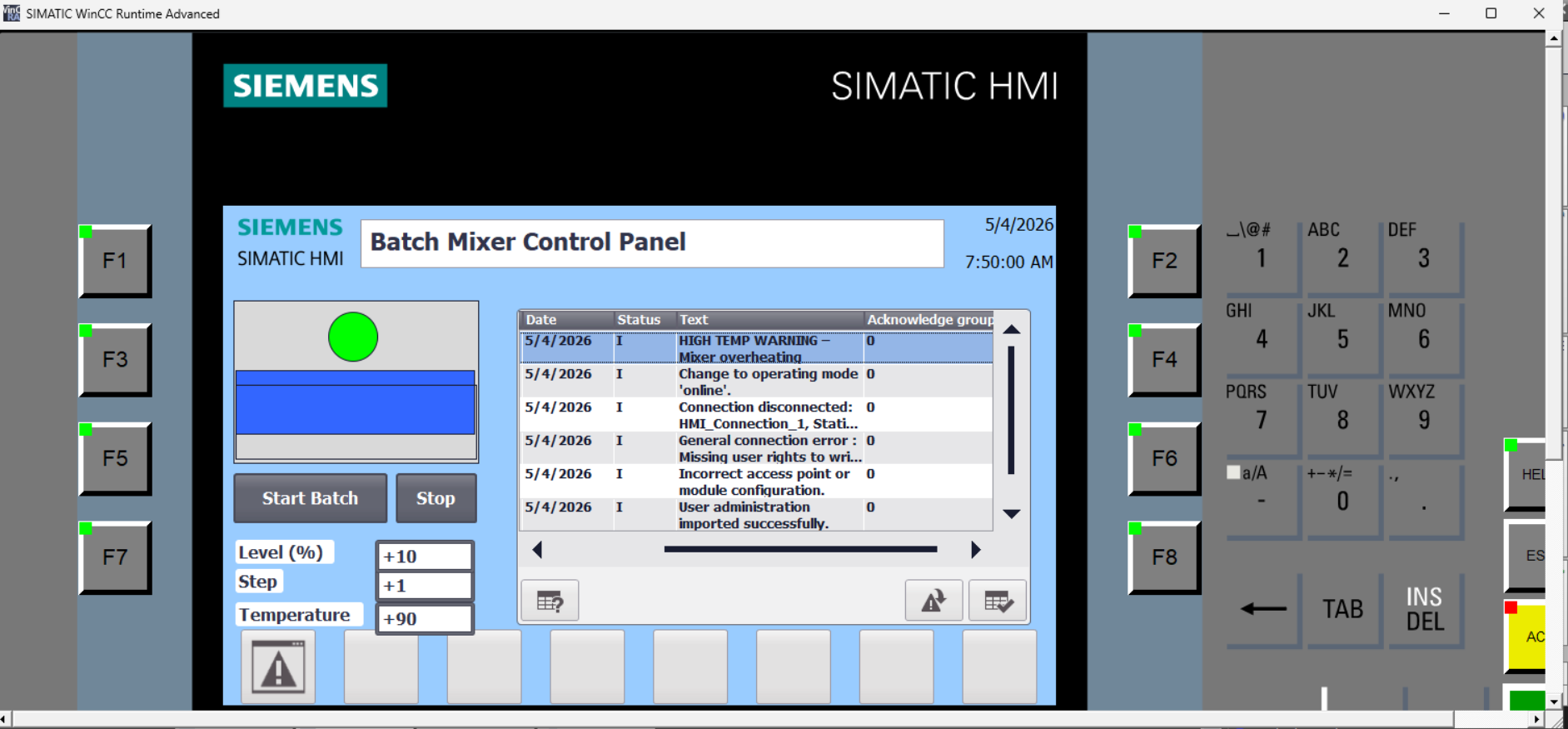
- Runtime launch: Root Screen renders correctly with all IO fields initialised; status indicator circle displays green when process state is active
- Tag simulation: Level, Step, and Temperature IO fields confirmed live-updating against simulated tag values (+10, +1, +90 respectively visible in runtime screenshot)
- Discrete alarm:
HighTempWarningforced to TRUE — "HIGH TEMP WARNING – Mixer overheating" appears in alarm buffer with correct timestamp, Status I (Info/Active), and acknowledge group 0 - Analogue alarm:
MixerTemperaturesimulated above 85 — upper-limit alarm fires independently of the Bool path, confirming dual-channel coverage - Diagnostics alarm population: alarm buffer correctly surfaces connection-level entries (disconnected, mode change, module configuration) alongside process alarms in a single chronological view, without requiring manual configuration of those entries
- Alarm persistence: after acknowledging the HIGH TEMP WARNING, the entry remains visible in buffer mode — confirmed the view is not configured in current-alarm mode
Challenges Faced
The most persistent challenge was alarm triggering behaviour during initial configuration. The HIGH TEMP WARNING alarm failed to appear in the runtime view despite the trigger tag being asserted. Root cause: the alarm view object had been placed in current-alarm mode rather than buffer mode, and the alarm was firing and immediately clearing before the operator could observe it. Switching to buffer mode and configuring the alarm trigger for rising-edge detection resolved the issue — the alarm now fires on the 0→1 transition and persists in the buffer until explicitly acknowledged.
The second challenge was the distinction between discrete and analogue alarm types. Initial attempts to configure the temperature alarm as a discrete Bool alarm produced incorrect trigger behaviour when the temperature tag was an Int rather than a Bool. Understanding that analogue alarms operate on threshold comparisons against numeric tags — not bit-level reads — required a structural reconfiguration of that alarm's trigger definition, switching from discrete to upper-limit analogue mode.
The third challenge was tag architecture hygiene. Early in development, several display tags were declared as HMI-internal tags and manually assigned test values, which masked genuine PLC-connection issues. Migrating all process-relevant tags to PLC-connected definitions — and using only @DiagnosticsIndicatorTag as an HMI-internal system tag — produced a clean separation that made subsequent debugging significantly more tractable.
TIA Portal's HMI compiler also surfaced non-obvious warnings when IO field format masks did not match the declared data type of the bound tag. Resolving these required aligning the display format (integer vs floating-point) with the PLC tag type, which in turn surfaced a type inconsistency between CurrentStep (Int) and an early IO field configured for Real display — corrected by standardising the tag type across the PLC interface and HMI binding.
Key Learning Outcomes
- Designing and implementing industrial operator interfaces using Siemens SIMATIC WinCC Comfort in TIA Portal
- HMI tag architecture: correctly separating PLC-connected tags from HMI-internal tags and understanding the data flow implications of each
- IO field binding, animation configuration, and event action assignment for buttons without HMI-side scripting
- Discrete alarm configuration: trigger tag, trigger bit, alarm class, alarm text, and acknowledge group assignment
- Analogue alarm configuration: upper-limit threshold detection against numeric PLC tags, independent of Bool flag logic
- Alarm buffer vs current-alarm view modes and the traceability implications of each for batch process logging
- WinCC diagnostics alarm architecture:
@DiagnosticsIndicatorTagand auto-generated connection-level fault surfacing - Dual-channel alarm coverage as a redundancy strategy: Bool flag path + raw analogue threshold path
- HMI / PLC separation of concerns: presentation layer owns display and operator input; PLC owns control logic and interlock evaluation
- Runtime validation in SIMATIC WinCC Runtime Advanced: simulating tag values, forcing alarm conditions, and validating buffer persistence
- TIA Portal compile cycle discipline: resolving format-mask / data-type mismatches and interpreting warning vs error distinction
- KP700 Comfort panel capability boundaries and how alarm architecture requirements drive panel hardware selection
Tools & Technologies
- Siemens TIA Portal V18 (Cloud)
- SIMATIC WinCC Comfort (HMI engineering environment)
- SIMATIC WinCC Runtime Advanced (runtime validation and simulation)
- KP700 Comfort HMI panel (7" keypad panel, WinCC Comfort target)
- S7-1212C DC/DC/DC (CPU, PLC side of HMI connection)
- GRAPH (IEC 61131-3 SFC) for PLC-side sequence control (GRAPH FB providing
S_NO/CurrentStepoutput) - TIA Portal HMI tag editor, alarm editor, and screen canvas
- WinCC Comfort animation and event action editors