Case Study: Solar Tracker Position Controller
Designing and implementing a closed-loop solar tracker control system in CODESYS using Structured Text (ST), angular position control, deadband hysteresis, hardware interlock protection, and dual-mode operation with manual override
Project Overview
This project delivers a fully functional closed-loop position controller for a single-axis solar tracking system, designed to simulate real-world photovoltaic (PV) panel orientation in industrial renewable energy applications. The tracker continuously computes the angular error between the target sun position and the current panel angle, driving motor outputs to minimise that error in real time.
The entire control application was engineered in Structured Text (ST) within the CODESYS V3.5 IEC 61131-3 environment. The implementation encompasses angular error computation, hysteresis-based deadband control to suppress motor chatter, hardware limit switch interlocking for mechanical overtravel protection, latching fault detection with conflict logic, and a full manual override mode designed to meet industrial maintenance safety requirements.
Problem
Photovoltaic systems operating under single-axis or dual-axis tracking must continuously servo their panel angle to the solar azimuth throughout the day to maximise irradiance capture. This introduces several control engineering challenges: without a movement tolerance band, even minor sensor noise or floating-point jitter causes continuous motor toggling, accelerating mechanical wear. Additionally, unrestricted motor actuation risks driving the tracker beyond its physical range of motion, causing structural damage or actuator failure. Finally, maintenance personnel require a safe, controlled manual positioning mode that retains all hardware safety interlocks and prevents operator input conflicts from causing undefined actuator behaviour.
Solution
- Sun_Position → Simulated solar azimuth input (REAL, 0–360°); represents setpoint signal from a sun-tracking algorithm or sensor
- Current_Position → Encoder or sensor feedback representing the tracker's actual angular position (REAL)
- Position_Error → Computed angular deviation: difference between setpoint and process variable; drives all motion decisions
- Motor_Left → Digital output commanding counter-clockwise rotation; active only when error is negative and left limit is not asserted
- Motor_Right → Digital output commanding clockwise rotation; active only when error is positive and right limit is not asserted
- Auto_Mode → Boolean flag enabling closed-loop sun-tracking; disabling this flag hands control to manual inputs
- Manual_Left / Manual_Right → Operator-initiated movement commands for maintenance positioning; both signals simultaneously asserted triggers a fault condition
- Left_Limit / Right_Limit → Hardware normally-open limit switch inputs; assertion blocks further movement in the corresponding direction and sets fault if both are active simultaneously
- Aligned → Status flag asserted when Position_Error falls within the ±Tolerance deadband; indicates acceptable tracking accuracy
- Fault → Latching fault output triggered by limit switch conflicts, simultaneous manual commands, or overtravel conditions; requires investigation before resuming operation
A symmetric deadband tolerance of ±2.0° was applied around the setpoint to implement hysteresis in the control loop. This prevents the classic bang-bang controller problem of high-frequency motor switching when the process variable oscillates near the setpoint. The approach mirrors standard industrial motion control practice, where a configurable dead zone is defined around the target to trade off tracking precision against actuator duty cycle and mechanical longevity.
Project Screenshots
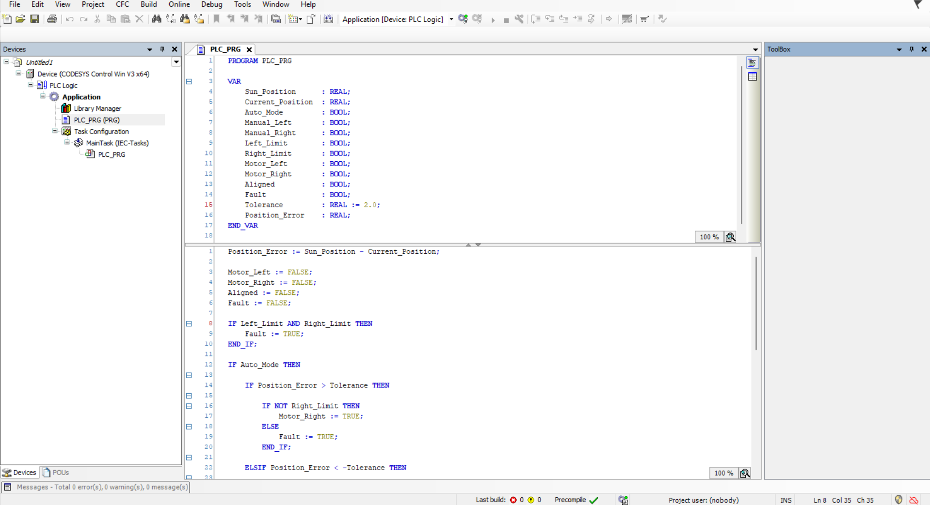
Variables Used
PROGRAM PLC_PRG

VAR
    Sun_Position      : REAL;
    Current_Position  : REAL;
    Auto_Mode         : BOOL;
    Manual_Left       : BOOL;
    Manual_Right      : BOOL;
    Left_Limit        : BOOL;
    Right_Limit       : BOOL;

    Motor_Left        : BOOL;
    Motor_Right       : BOOL;
    Aligned           : BOOL;
    Fault             : BOOL;

    Tolerance         : REAL := 2.0;
    Position_Error    : REAL;
END_VAR
Core Structured Text Logic
Position_Error := Sun_Position - Current_Position;
Motor_Left := FALSE;
Motor_Right := FALSE;
Aligned := FALSE;
Fault := FALSE;
IF Left_Limit AND Right_Limit THEN
Fault := TRUE;
END_IF;
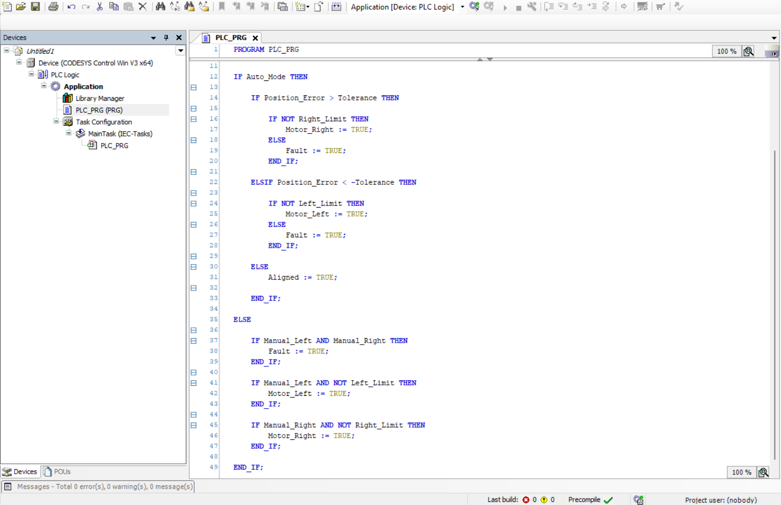
IF Auto_Mode THEN
IF Position_Error > Tolerance THEN
IF NOT Right_Limit THEN
Motor_Right := TRUE;
ELSE
Fault := TRUE;
END_IF;
ELSIF Position_Error < -Tolerance THEN
IF NOT Left_Limit THEN
Motor_Left := TRUE;
ELSE
Fault := TRUE;
END_IF;
ELSE
Aligned := TRUE;
END_IF;
ELSE
IF Manual_Left AND Manual_Right THEN
Fault := TRUE;
END_IF;
IF Manual_Left AND NOT Left_Limit THEN
Motor_Left := TRUE;
END_IF;
IF Manual_Right AND NOT Right_Limit THEN
Motor_Right := TRUE;
END_IF;
END_IF;
Testing & Debugging
Verification was conducted using CODESYS Online Mode with live variable monitoring and forced I/O simulation to validate all control paths without requiring physical hardware. Each branch of the control logic was exercised systematically against a defined test matrix covering normal operation, boundary conditions, and fault scenarios.
- Sun_Position was swept across the full 0–360° range to validate error computation accuracy and correct motor output assertion across all angular regions
- Position_Error was monitored continuously in the Watch Window to confirm the deadband correctly suppressed motor outputs within the ±2.0° tolerance zone
- Left_Limit and Right_Limit inputs were force-toggled individually and simultaneously to verify interlock behaviour, overtravel blocking, and simultaneous-assertion fault detection
- Manual mode was isolated and tested for correct single-direction movement, limit switch enforcement during maintenance positioning, and operator conflict detection
- Fault state was triggered via both hardware interlock conflicts and simultaneous manual command injection to confirm latching behaviour
- Aligned flag was validated to assert only within the deadband and deassert correctly upon setpoint deviation exceeding the tolerance threshold
Challenges Faced
The primary control engineering challenge was eliminating motor chatter inherent to a simple bang-bang position controller. Without a tolerance band, floating-point comparison of two REAL values oscillating around a setpoint produces continuous, alternating motor outputs — a condition that is mechanically destructive and electrically wasteful in practice. Implementing symmetric deadband hysteresis resolved this by defining an acceptable steady-state error window, within which the controller takes no corrective action, substantially reducing actuator switching frequency.
A secondary challenge was ensuring that transitioning to manual override mode did not degrade the system's safety integrity. In naive implementations, manual mode bypasses all automated safety logic, creating overtravel risk during maintenance. The solution was to retain full hardware interlock enforcement in the manual branch — limit switch checks remain active regardless of operating mode — while adding an additional layer of operator conflict detection to prevent simultaneous opposing commands from producing undefined actuator behaviour. This design pattern aligns with IEC 62061 safety function requirements for industrial machinery.
Key Learning Outcomes
- IEC 61131-3 Structured Text (ST) development and structured programming practices in CODESYS
- Closed-loop position error calculation and deadband hysteresis implementation for motor stability
- Dual-mode control architecture design (Automatic closed-loop / Manual maintenance override)
- Hardware safety interlock integration using normally-open limit switch logic
- Fault detection design covering hardware conflicts, operator input errors, and overtravel conditions
- Renewable energy system control design principles applicable to single-axis PV tracker applications
Tools Used
- CODESYS V3.5 SP22 — IEC 61131-3 compliant PLC development environment
- CODESYS Control Win — Software PLC runtime for PC-based simulation and validation
- Structured Text (ST) — Primary implementation language for all control logic
- CODESYS Online Monitoring and Force Table — Live variable inspection and I/O simulation for test and debug
- Renewable energy position control simulation — Angular setpoint tracking logic modelled on real single-axis PV tracker behaviour