Case Study: Solar Tracker HMI Visualization
Integrated PLC and HMI design for a single-axis solar tracker, implemented in IEC 61131-3 Structured Text with a CODESYS-native operator visualization layer
Project Overview
This project delivers a complete supervisory control package for a single-axis solar tracker — both the underlying PLC control program and the operator-facing HMI used to monitor and command it. The control logic is written in IEC 61131-3 Structured Text (ST) and the visualization is built using CODESYS Visualization, which compiles HMI elements directly against the same symbol table as the PLC program. This guarantees a single source of truth between runtime data and the operator interface.
The system supports both an automatic closed-loop tracking mode that drives the panel toward a computed sun position, and a manual jog mode for commissioning, maintenance, and fault recovery. Movement is bounded by hardware end-of-travel limit switches and a software dead-band tolerance to prevent hunting around the setpoint.
Problem
A solar tracker must continuously align its panel normal with the incident solar vector to maximize irradiance capture, while protecting itself and the operator under all conditions. From a control-systems perspective this introduces several distinct requirements that must coexist in the same program: a closed-loop position controller with deterministic dead-band behavior to suppress oscillation around the setpoint; hard-stop interlocks at both end-of-travel limits that remain authoritative regardless of operator commands; safe transitions between automatic and manual modes without producing unintended motor activation; and an operator interface that exposes meaningful state without granting unrestricted write access to the underlying PLC tags. The HMI in particular must present commands and feedback in a way that is unambiguous under fault conditions and safe to use during a live process.
Solution
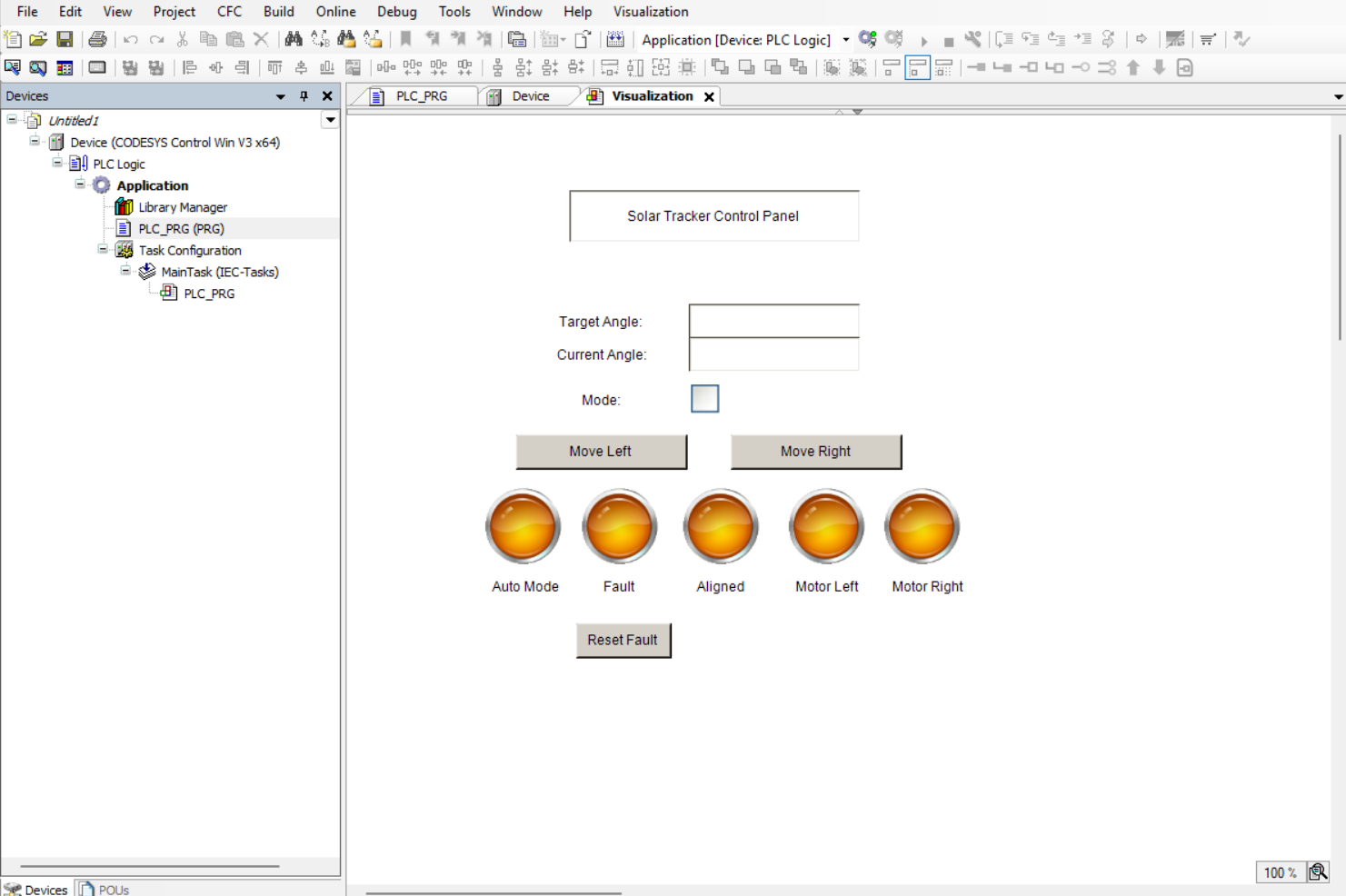
- Auto Mode — closed-loop tracking that drives Position_Error (Sun_Position − Current_Position) toward zero within a configurable Tolerance dead-band
- Manual Jog (Left / Right) — momentary commands gated by the active limit switch on each side, so operator input cannot drive the actuator past mechanical end-of-travel
- Position Display — live numeric readout of both Target (Sun_Position) and Current_Position, with computed Position_Error visible to the operator
- End-of-Travel Interlocks — Left_Limit and Right_Limit inputs immediately de-energize the corresponding motor output regardless of mode
- Fault Detection and Reset — latched Fault flag with operator-acknowledged reset (Reset_Fault) to prevent silent fault clearing
- Status Indication — discrete lamps for Aligned, Motor_Left, Motor_Right, and Fault, providing at-a-glance operational state without requiring the operator to read raw values
Mode arbitration is structured so that Auto_Mode and the manual jog buttons are mutually exclusive — manual commands are only honored when Auto_Mode is FALSE, preventing race conditions between the closed-loop controller and direct operator input. The HMI binds only to a curated set of command tags (Auto_Mode, Manual_Left, Manual_Right, Reset_Fault) rather than the full variable list, which keeps the operator surface narrow and well-defined while leaving internal state read-only on the visualization layer.
Project Screenshots
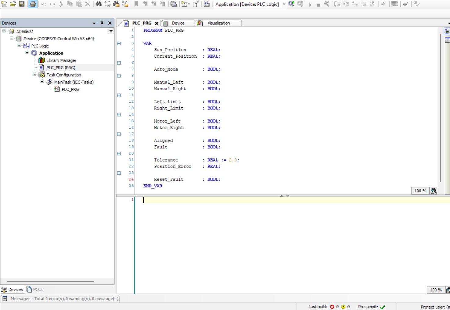
Variables Used
VAR
    (* Process variables - position feedback and setpoint *)
    Sun_Position      : REAL;          (* Computed solar azimuth setpoint, degrees *)
    Current_Position  : REAL;          (* Encoder feedback of panel position, degrees *)
    Position_Error    : REAL;          (* Sun_Position - Current_Position *)
    Tolerance         : REAL := 2.0;   (* Dead-band, degrees - prevents hunting   *)

    (* Mode selection *)
    Auto_Mode         : BOOL;          (* TRUE = closed-loop, FALSE = manual      *)

    (* Operator command inputs from HMI *)
    Manual_Left       : BOOL;          (* Momentary jog command, west             *)
    Manual_Right      : BOOL;          (* Momentary jog command, east             *)
    Reset_Fault       : BOOL;          (* Operator-acknowledged fault clear       *)

    (* Hardware safety inputs *)
    Left_Limit        : BOOL;          (* End-of-travel limit switch, west        *)
    Right_Limit       : BOOL;          (* End-of-travel limit switch, east        *)

    (* Motor outputs to drive *)
    Motor_Left        : BOOL;          (* DO - rotate west *)
    Motor_Right       : BOOL;          (* DO - rotate east *)

    (* Status flags for HMI feedback *)
    Aligned           : BOOL;          (* TRUE when |Position_Error| <= Tolerance *)
    Fault             : BOOL;          (* Latched fault condition                 *)
END_VAR
Testing & Debugging
Validation was carried out against the CODESYS soft-PLC runtime in online mode, using forced variable injection to simulate field signals (encoder feedback, limit switches, sun-position setpoint) without physical hardware in the loop. Each operating mode and fault path was exercised independently and observed against expected behavior on both the program side and the HMI side.
- Manual jog commands correctly energized Motor_Left and Motor_Right and were inhibited at the corresponding limit switch as expected
- HMI status lamps tracked motor and fault state in real time with no observable lag against the underlying PLC tags
- Limit switches latched the Fault flag under simulated over-travel conditions, holding the system out of motion until acknowledged
- Reset_Fault cleared the latched Fault and restored normal operation only when the underlying limit condition had been resolved
- Auto mode drove Position_Error to within the configured Tolerance dead-band and asserted Aligned without oscillating across the setpoint
- Mode transitions between Auto and Manual produced no spurious motor pulses at the switchover instant
Challenges Faced
The most substantial learning curve was the CODESYS Visualization editor itself — specifically, the distinction between an HMI element's input configuration (which tag is written) and its output configuration (which tag drives its appearance), and how those bindings differ across element types. Buttons, lamps, and checkboxes each expose a different surface for variable linkage, and getting the binding direction wrong produced elements that looked correct visually but behaved as either read-only displays or write-only commands. Building a stable mental model of bidirectional tag binding required several iterations and careful inspection of the property dialogs.
Beyond the tooling, the harder challenge was thinking about the HMI as a true operator interface rather than a debug surface. That meant deliberately limiting which tags the HMI could write to, ensuring fault states could not be silently cleared, and making sure every visible element communicated unambiguous information under both normal and degraded operating conditions. This shifted the design from "what can the operator see" to "what can the operator safely do."
Key Learning Outcomes
- CODESYS Visualization editor workflow, element property model, and tag-binding semantics
- HMI design discipline for industrial operator interfaces, including curated write-surfaces and fail-safe acknowledgement patterns
- Bidirectional PLC-to-HMI variable linking and the distinction between command tags and status tags
- Manual/automatic mode arbitration and the use of software interlocks alongside hardware limit switches
- Latched fault handling with operator-acknowledged reset, following standard industrial safety patterns
- Structured Text logic for closed-loop motion control with dead-band tolerance to suppress hunting
- Systems-level thinking about how PLC behavior, HMI presentation, and operator workflow interact in a real installation
Tools Used
- CODESYS Development System V3
- IEC 61131-3 Structured Text (ST)
- CODESYS Visualization (integrated HMI editor)
- CODESYS soft-PLC runtime simulation with online monitoring and forced variables
- Industrial HMI design principles — interlocking, fail-safe acknowledgement, and operator-surface scoping