Siemens Smart Solar Plant
SCADA System
A modular industrial renewable energy simulation platform engineered in Siemens TIA Portal V19 on an S7-1500 PLC architecture — implementing real-time environmental simulation, layered energy management, battery storage logic, and smart grid balancing within a fully virtualised PLCSIM commissioning environment.
Project Overview
This project constructs a virtualised renewable energy microgrid simulation using Siemens' industrial automation stack. Designed from the ground up as a scalable, SCADA-ready system, it models the behaviour of a modern solar utility installation — from environmental input processing through to grid export decisions — entirely within a software-defined PLC runtime.
The architecture enforces strict separation of concerns across simulation, energy generation, storage, and control layers. Each subsystem is implemented as an independent Function Block with dedicated instance Data Blocks, following professional Siemens object-oriented PLC engineering methodology.
Software Environment
| Component | Technology |
|---|---|
| PLC Platform | Siemens S7-1500 (CPU 1511-1 PN) |
| Engineering Environment | TIA Portal V19 |
| Simulation Environment | Siemens PLCSIM V19 |
| Programming Language | SCL (Structured Control Language) |
| HMI / SCADA Target | WinCC Unified (Phase 2) |
System Architecture
The project follows a strict top-down layered industrial architecture. Each layer consumes outputs from the layer above it, maintaining clean data flow and enabling independent testing of every subsystem.
PLC Project Structure
The program block organisation mirrors professional Siemens industrial project conventions, with dedicated folders segregating simulation, energy, control, alarms, utilities, data types, and testing logic:
00_Main        — Execution entry point (OB1)
01_Simulation  — Environmental simulation FBs
02_Energy      — Solar array + battery FBs
03_Control     — Grid management control logic
04_Alarms      — Alarm handling (Phase 3)
05_Utilities   — Shared utility functions
06_DataTypes   — UDT definitions
07_Testing     — Watch tables and commissioning tools
Data Architecture
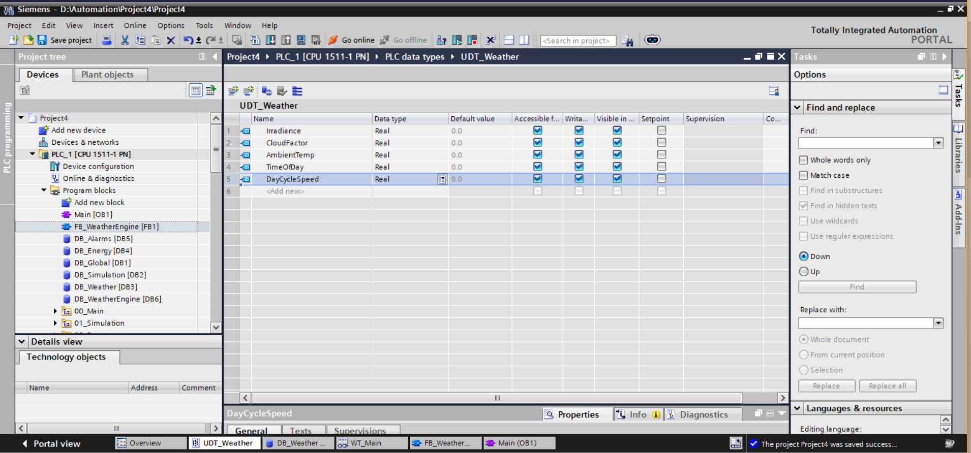
All process data is structured using User Defined Types (UDTs), providing strongly-typed, scalable data models consistent with industrial SCADA engineering standards. Global Data Blocks act as shared memory accessible across all Function Blocks.
Irradiance— Simulated solar irradiance (W/m²)CloudFactor— Dynamic cloud attenuation coefficientAmbientTemp— Ambient temperature (°C)TimeOfDay— Simulated 24-hour clock valueDayCycleSpeed— Accelerated time progression scalar
Generated_kW,Efficiency,Voltage,Current,FrequencyGridImport_kW,GridExport_kW
SOC— State of charge (%)ChargeRate,DischargeRate,BatteryTemp,Mode
UDT_Alarm reserved for Phase 3 fault handling.
Function Block Architecture
FB_WeatherEngine [FB1] — Weather Simulation Engine
Simulates a complete 24-hour environmental cycle using SCL. Computes irradiance via a piecewise daylight curve, applies cloud attenuation, and drives ambient temperature — all at an accelerated simulation rate for rapid commissioning validation.
- Simulated 24h cycle with day/night transitions and automatic reset
- Piecewise irradiance model:
(SimTime - 6.0) × 100.0during solar hours, clamped to 1,000 W/m² - Dynamic cloud factor modulates effective irradiance in real time
- Outputs:
IrradianceOut,CloudOut,TempOut,TimeOut→ written toDB_Weather.WeatherData
FB_SolarArray [FB2] — Solar Generation Engine
Calculates dynamic solar power production from live weather inputs. Models panel efficiency degradation under cloud cover and derives simulated electrical output parameters consistent with a grid-tied inverter model.
- Inputs:
IrradianceIn,CloudFactorInfromDB_Weather - Outputs:
Generated_kW,Efficiency,Voltage,Current,Frequency→DB_Energy.PowerData
FB_BatterySystem [FB3] — Battery Energy Storage System
Implements charge/discharge logic with full state-of-charge tracking and thermal simulation. Battery mode switches dynamically based on available solar generation — charging under surplus, discharging under deficit.
- Input:
GeneratedPowerInfrom solar generation layer - Outputs:
SOC_Out,ChargeRateOut,BatteryTempOut,ModeOut→DB_Energy.BatteryData
FB_GridManager [FB4] — Smart Grid Management System
Implements microgrid energy balancing logic. Evaluates real-time solar generation and battery SOC to determine optimal grid interaction mode — exporting surplus capacity, importing when generation is insufficient, or operating autonomously in balanced state.
- Inputs:
SolarPowerIn(Generated_kW),BatterySOC_In - Outputs:
GridImportOut,GridExportOut,GridModeOut→DB_Energy.PowerData - Excess solar: exports surplus to utility grid
- Low generation + low SOC: imports from utility grid
- Balanced state: operates autonomously without import/export
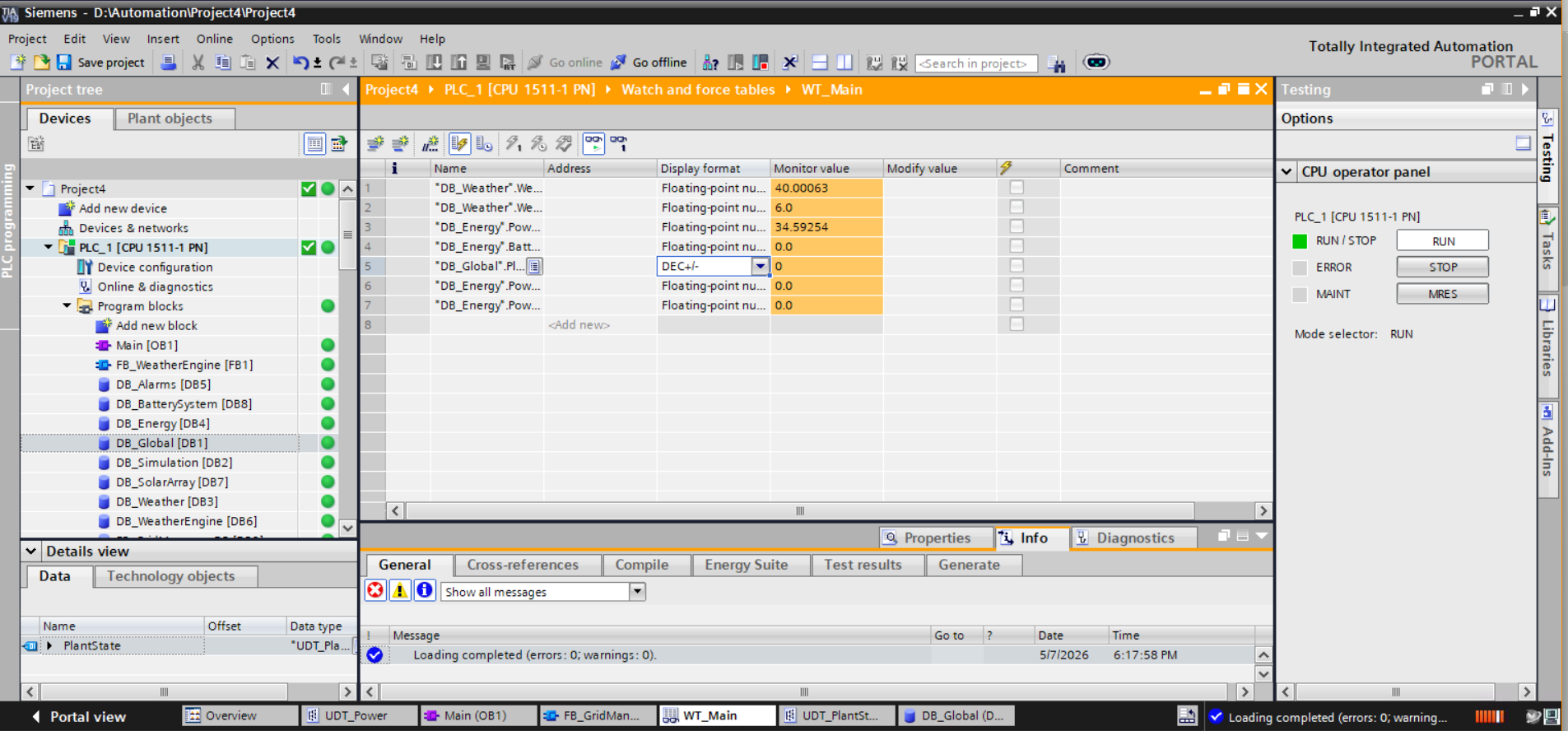
Project Screenshots
All screenshots captured from live PLCSIM runtime session — project in RUN state with active watch table monitoring.
![Main [OB1] — Network 1: FB_WeatherEngine instantiated with DB_WeatherEngine [DB6]](../assets/Screenshot_2026-05-07_171158.png)
![FB_WeatherEngine [FB1] — SCL implementation of the 24-hour time progression loop](../assets/Screenshot_2026-05-07_171218.png)
![Main [OB1] — Network 2: FB_SolarArray (FB2)](../assets/Screenshot_2026-05-07_174106.png)
![Main [OB1] — Network 3: FB_BatterySystem (FB3)](../assets/Screenshot_2026-05-07_175135.png)
![Main [OB1] — Network 4: FB_GridManager (FB4)](../assets/Screenshot_2026-05-07_181537.png)
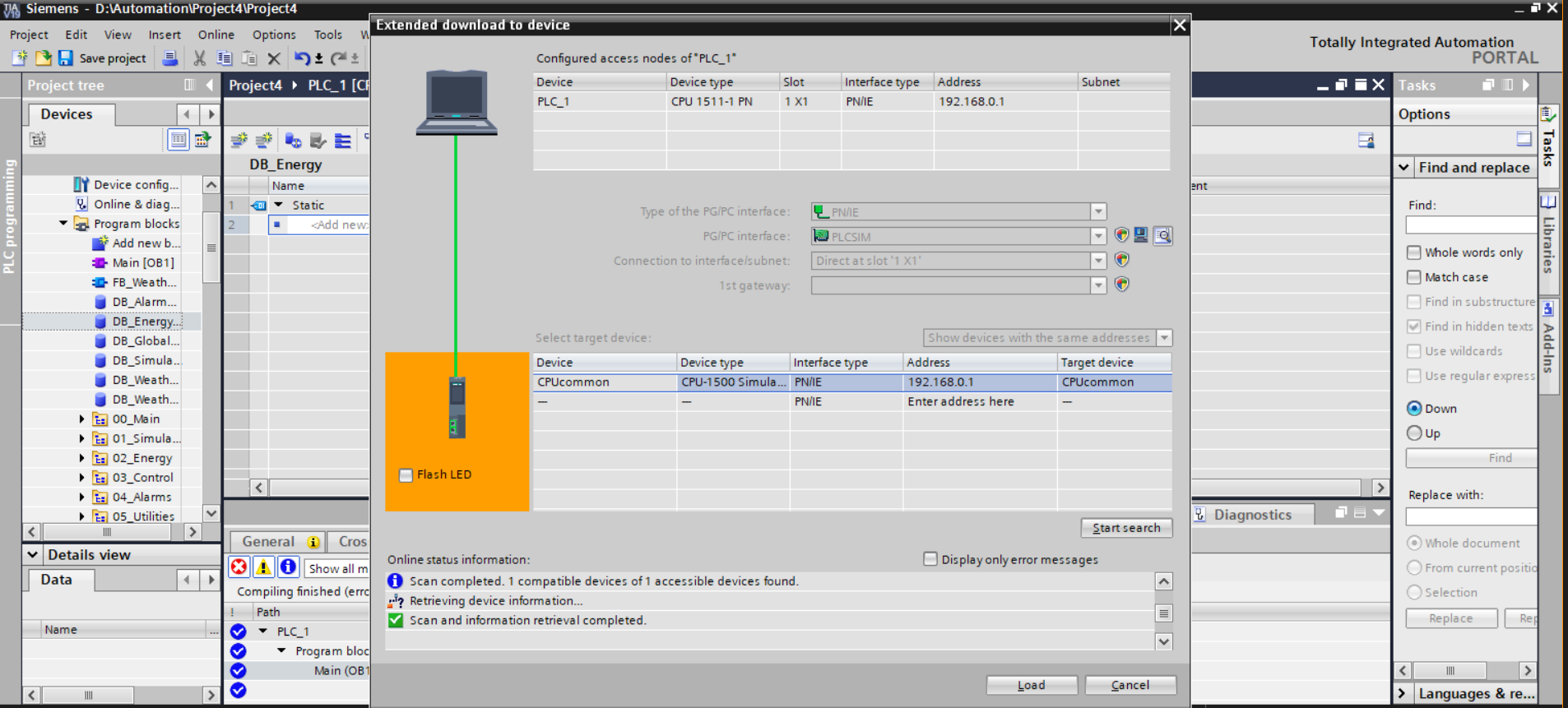
Virtual Commissioning & Runtime Validation
The complete system was deployed to a Siemens PLCSIM virtual PLC instance via TIA Portal's Extended Download workflow. The CPU 1511-1 PN simulator was configured at 192.168.0.1 via PN/IE interface. All program blocks compiled to zero errors; the PLC entered RUN state with all Data Blocks online and green-flagged.
- Live irradiance and time-of-day monitoring from
DB_Weather.WeatherData - Real-time solar generation readout from
DB_Energy.PowerData.Generated_kW - Battery SOC live tracking from
DB_Energy.BatteryData.SOC - Plant state enum monitoring via
DB_Global.PlantState - Grid import/export values visible for real-time energy balance validation
Current System Capabilities
- Simulates full 24-hour environmental weather cycle with dynamic irradiance and cloud coverage
- Generates dynamic solar power output from live weather inputs with efficiency modelling
- Simulates battery charging and discharging with state-of-charge tracking and thermal behaviour
- Executes smart grid import/export balancing logic based on generation and storage state
- Runs entirely within Siemens PLCSIM virtual PLC runtime — no physical hardware required
- Provides live runtime monitoring via centralised WT_Main watch table
- Fully modular FB architecture — each subsystem independently testable and reusable
- Structured UDT/DB data model consistent with industrial SCADA tag architecture
Development Roadmap
✅ Phase 1 — Core Simulation
Weather engine, solar generation, BESS, grid manager. Full PLCSIM virtual commissioning. Complete.
➡ Phase 2 — WinCC Unified SCADA
Operator overview screens, animated power flow diagrams, battery indicators, solar dashboards, trend visualisation.
Phase 3 — Alarm & Fault Handling
Inverter faults, overtemperature alarms, grid instability simulation, alarm acknowledgment workflows.
Phase 4 — Historical Trends
Energy historian, 24h accelerated playback, trend logging and reporting.
Phase 5 — Hybrid Microgrid
Wind turbine simulation, diesel generator backup, automatic transfer switching logic.
Phase 6 — Advanced Control
Plant state machines, PID thermal control, predictive optimisation, operational recipes.