Case Study: S7-1200 Start/Stop Motor (TIA Portal)
A foundational Siemens TIA Portal implementation of an IEC 61131-3 compliant start/stop motor control system using symbolic absolute addressing, a structured PLC tag table, and a seal-in (latching) ladder logic circuit — designed to mirror real-world industrial motor control standards
Project Overview
This project establishes core competency in the Siemens TIA Portal development environment by implementing a production-representative motor control circuit on an S7-1200 PLC. The primary objective was to understand how Siemens structures hardware configuration, memory organisation, and program execution across its Step 7 ecosystem — and to identify where that workflow diverges from platforms like CODESYS.
The system implements a standard industrial latch circuit (seal-in), a design pattern found in virtually every motor control panel in manufacturing, water treatment, and process automation environments. The circuit ensures that a momentary start signal latches the motor output, while a normally-closed stop input provides a fail-safe shutdown path that cannot be overridden by software.
Problem
Industrial motor control demands deterministic, fault-tolerant behaviour that simple toggle logic cannot provide. A momentary push button must start a motor and hold it energised independently of operator input. Simultaneously, the stop circuit must be architecturally incapable of failing into a "run" state — a requirement that mandates the use of a normally-closed (NC) input rather than a software-only interlock.
The engineering requirements were therefore:
- Implement a latching output that persists after the start signal de-energises, without using internal flags or data blocks
- Wire the stop condition as a normally-closed contact so that a wiring fault, broken wire, or open circuit always defaults to a safe stop — not a runaway motor
- Use symbolic tag addressing throughout to produce maintainable, self-documenting code aligned with IEC 61131-3 naming conventions
Solution Architecture
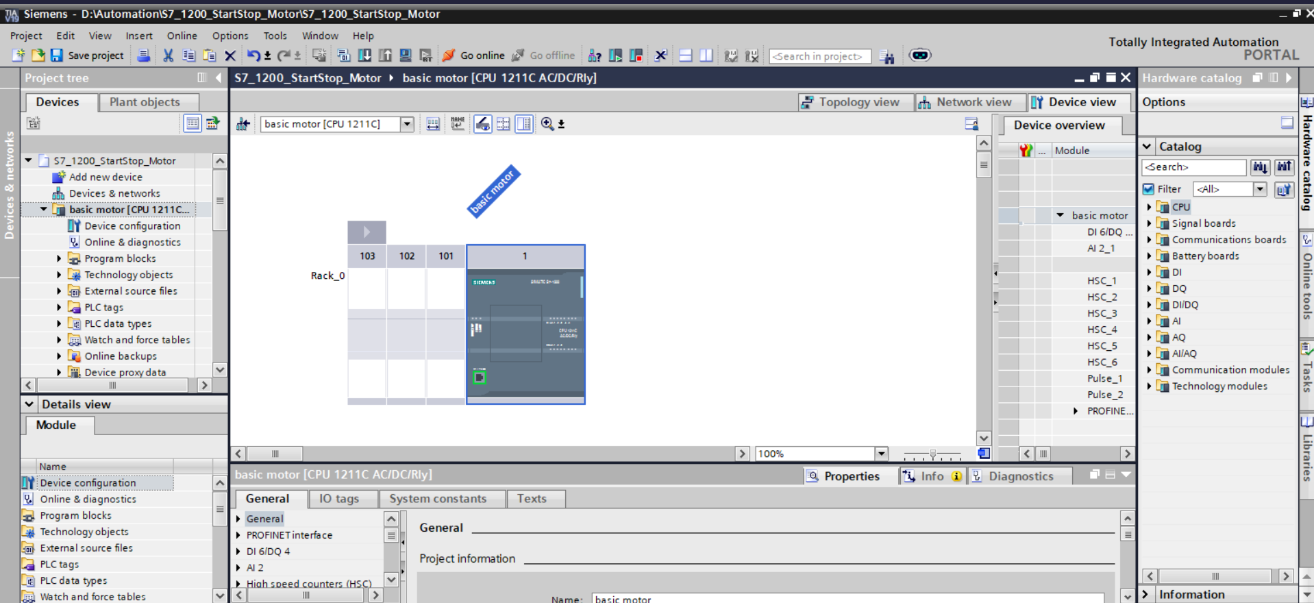
- S7-1200 CPU 1211C configured in TIA Portal with correct firmware version and I/O addressing
- Digital input module mapped to physical terminal block connections for start and stop push buttons
- Digital output module mapped to the motor contactor coil circuit
- Hardware configuration compiled and downloaded to the CPU before program execution — a required sequence in TIA Portal that differs from CODESYS's softer separation between hardware and software
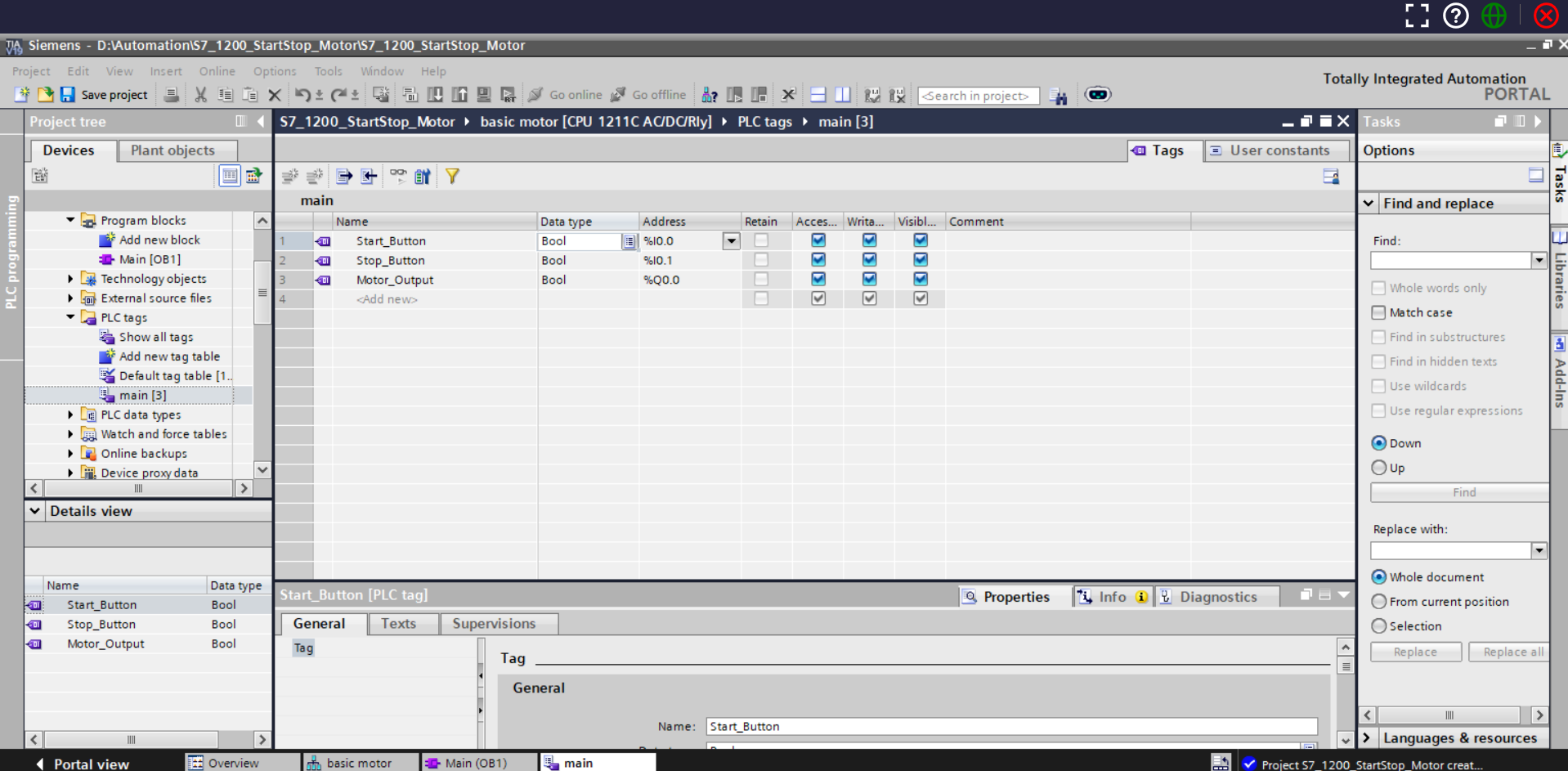
Start_Button → %I0.0— Normally open digital input; momentary contactStop_Button → %I0.1— Normally closed digital input; fail-safe stop pathMotor_Output → %Q0.0— Digital output coil driving the motor contactor- All tags defined in the default PLC tag table, enabling symbolic reference throughout the program without hardcoding addresses in ladder rungs
- Normally closed
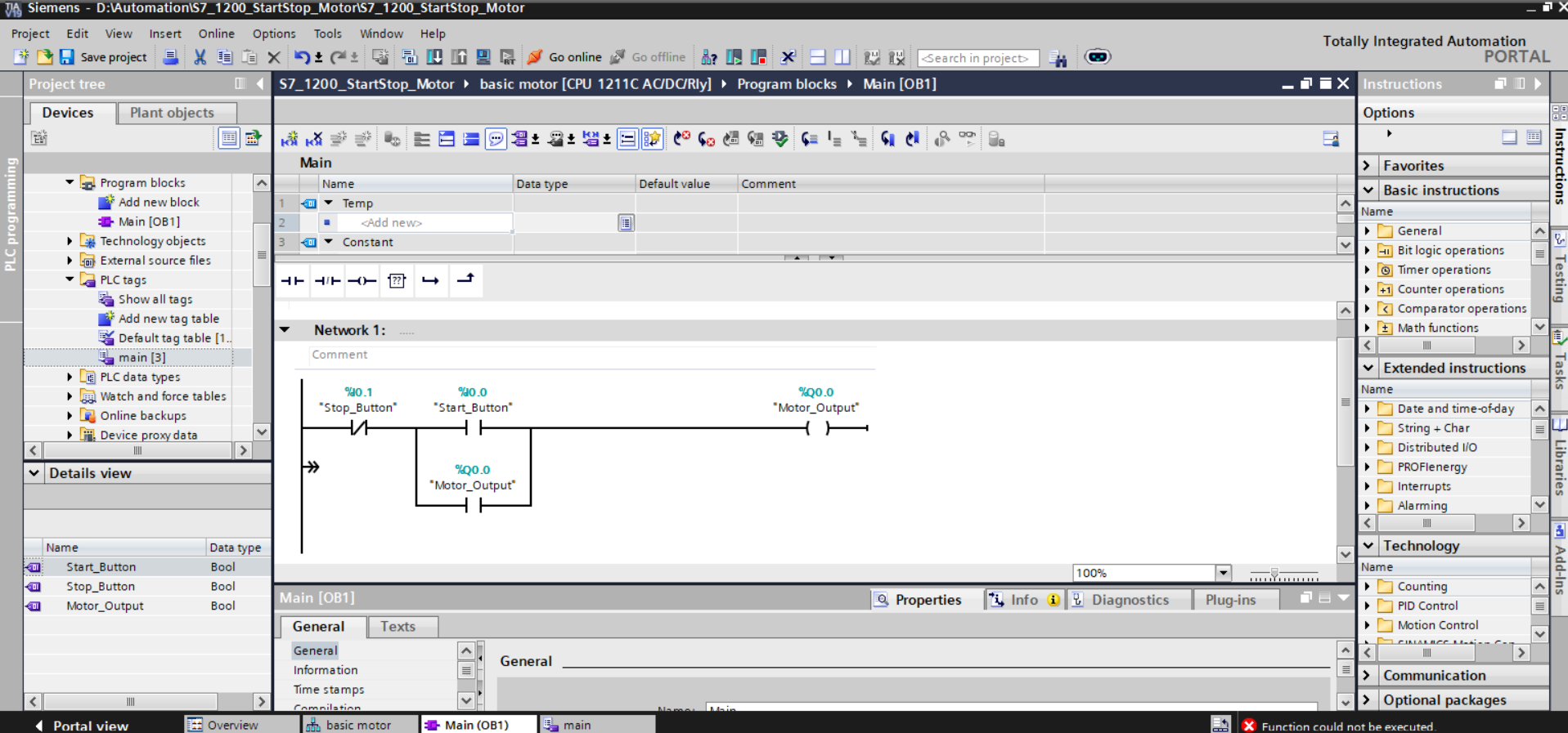
Stop_Buttonplaced first in the rung — ensures the stop condition is evaluated before any energisation logic, consistent with industrial safety conventions - Normally open
Start_Buttonin series — a momentary pulse closes this contact and energises the output coil - Parallel branch using
Motor_Outputas a self-seal contact — once the coil energises, it holds its own circuit closed independently of the start button - Output coil assigned to
Motor_Output (%Q0.0)— drives the physical contactor
The choice to use a hardware normally-closed input for stop — rather than a normally-open input inverted in software — reflects real-world panel wiring practice. A broken wire to a software-inverted input would read as "button pressed" and never stop the motor. With a physical NC input, the same broken wire opens the rung and the motor de-energises. Safety is encoded in the circuit topology, not in software assumptions.
Project Screenshots
Ladder Logic — Rung Structure Breakdown
| Stop (NC) | Start (NO) |----+----( Motor_Output )
                              |
                    +---------+
                    | Motor_Output (NO) |
                    +---------+
The rung evaluates left to right on every CPU scan cycle. The execution model is worth understanding precisely:
- Stop_Button (NC): Normally passes power — the rung is live by default. Pressing stop opens this contact and immediately breaks the entire rung, de-energising the output regardless of any other contact state.
- Start_Button (NO): Closed only while the button is held. On the first scan where it closes, power flows through to the output coil, energising
Motor_Output. - Motor_Output (seal-in branch): Because the output is now energised, its own contact in the parallel branch also closes. On the next scan — even after the start button opens — the motor self-feeds through this branch.
- De-energisation: Only
Stop_Button(NC) opening, or a power loss, can break the latch. The self-seal branch has no independent off-path.
Engineering Decisions Worth Calling Out
Several choices here reflect deliberate industrial design thinking rather than just minimum viable ladder logic:
- NC stop contact placed first in the rung. Evaluating the stop condition before the start or seal-in contacts ensures the CPU prioritises shutdown on every scan. This matches the left-to-right power flow model of IEC 61131-3 LAD and is the convention expected by panel builders and safety auditors.
-
Self-seal uses the output coil's own contact, not an internal flag. Using
Motor_Outputdirectly as the seal-in contact avoids introducing a separate internal memory bit, which would add a dependency that could desync if the output coil were forced or overridden. The latch is structurally tied to the physical output state. -
Symbolic addressing over hardcoded absolutes. Writing
Stop_Buttonin a rung is maintainable; writing%I0.1is not. If hardware is rewired and the input moves to%I0.3, only the tag table entry needs updating — not every rung that references it.
Challenges Faced
The primary challenge was internalising the Siemens-specific separation between hardware configuration and program execution. In TIA Portal, the hardware must be fully configured, compiled, and downloaded to the CPU before the program will run — the device tree and software project are tightly coupled. CODESYS allows a softer workflow where the program can be tested in simulation without a fully resolved hardware config. Understanding this distinction was essential to avoiding compile errors and failed downloads early in the project.
A secondary challenge was working within TIA Cloud's simulation constraints. The PLCSIM Advanced environment available locally provides force tables, watch tables, and I/O simulation; the cloud equivalent has limitations on which simulation features are accessible. This required planning test cases more deliberately before execution rather than relying on live forcing to debug ladder state.
Key Learning Outcomes
- Navigating TIA Portal's project structure: device configuration, program blocks, and tag management as distinct but linked layers
- Configuring S7-1200 hardware correctly including CPU selection, I/O module assignment, and address compilation
- Applying symbolic absolute addressing in the PLC tag table to produce self-documenting, maintainable programs
- Implementing a seal-in (latching) circuit using IEC 61131-3 ladder logic with correct contact topology
- Understanding why the normally-closed stop input is a physical safety convention — not a stylistic preference
- Identifying execution model differences between Siemens Step 7 and CODESYS-based environments
Tools & Technologies
- Siemens TIA Portal (Cloud)
- S7-1200 PLC (CPU 1211C)
- Ladder Logic (LAD) — IEC 61131-3
- Symbolic Tag Addressing
- PLCSIM (simulation environment)