Case Study: FB_BatchMixer SFC
A complete sequential batch automation system implemented as a Function Block (FB1) in Siemens TIA Portal using the GRAPH programming language (IEC 61131-3 Sequential Function Chart) — covering step-transition sequencing, sensor-gated transitions, time-based process control, and cyclic reset logic on an S7-1511C-1 PN CPU
Project Overview
FB_BatchMixer [FB1] implements a six-step sequential batch process within a Siemens S7-1511C-1 PN PLC, using the GRAPH programming language. The function block is called from Main [OB1] and manages the complete lifecycle of a mixing batch: from idle standby through tank filling, mixing, dispensing, cleaning, and automatic cyclic reset.
GRAPH was chosen deliberately over LAD or SCL alternatives because batch processes are inherently sequential — each stage must complete before the next begins. Implementing this as a flat LAD network would require manual interlock logic between every stage, producing brittle, hard-to-audit code. GRAPH enforces sequentiality at the language level: a step cannot become active unless its preceding transition is satisfied, eliminating an entire class of interlock errors by design. This is the same architecture used in industrial pharmaceutical, food processing, and chemical manufacturing plants.
Problem
A batch mixing process requires strict ordering of operations: both tanks must fill before mixing begins, mixing must run for a defined duration before dispensing, and the system must clean before restarting. The engineering challenge was therefore:
- Enforce step ordering without manual interlocking between every stage
- Gate transitions on actual physical sensor state, not assumed timing
- Implement a reliable 60-second mixing hold that resets cleanly on each cycle
- Return the sequence to idle automatically after cleaning, supporting continuous production runs
- Expose the current step number and key sensor signals to an HMI panel for operator visibility
Sequence Definition
The GRAPH sequence consists of six steps connected by six transitions, forming a single linear sequence with a cyclic return from T6 → S1. The Navigation panel confirms the full chain. Each transition is implemented as a LAD rung embedded within GRAPH.
| Step | Name | Transition Condition | Action / Purpose |
|---|---|---|---|
| S1 | S_Idle | #Start_Button (NO contact) |
Await operator start signal. System holds here until button is pressed. |
| S2 | S_FillA | #TankA_Level_High |
Open Valve A and fill Tank A. Transition fires on level sensor, not a timer. |
| S3 | S_FillB | #TankB_Level_High |
Open Valve B and fill Tank B. Tank A valve de-energises automatically on step exit (N qualifier). |
| S4 | S_Mix | #S_Mix.T > T#60s |
Enable mixer motor. Duration controlled by GRAPH's native step elapsed time — no external TON required. |
| S5 | S_Dispense | #Tank_Empty |
Open dispense valve and drain. Transition waits on the empty sensor — prevents advancing before drain completes. |
| S6 | S_Clean | #Clean_Done → S1 |
CIP rinse cycle. On assertion, T6 routes the sequence pointer back to S1, completing the cyclic batch loop. |
Solution Architecture
- Operator commands:
Start_Button,OFF_SQ,INIT_SQ,ACK_EF - Sensor inputs:
Tank_Empty,TankA_Level_High,TankB_Level_High,Clean_Done— all marked HMI-visible (Accessible / Writable / Visible) - Mode selectors:
SW_AUTO,SW_TAP,SW_TOP,SW_MAN— standard GRAPH operating mode flags for auto, tap, top-of-cycle, and manual modes - Sequence navigation:
S_PREV,S_NEXT,S_SEL(Int),S_ON,S_OFF,T_PUSH— for manual step-through during commissioning without modifying the FB
S_NO(Int) — current active step number, wired to HMI for live sequence position display ("Step 4 — Mixing" rather than just "Running")Valve_A(Bool) — primary actuator output; HMI-visible and writable for manual override during commissioningS_MORE,S_ACTIVE(Bool) — GRAPH diagnostic outputs indicating sequence presence and activity state, available to the diagnostic buffer
- GRAPH over LAD. Only the active step's actions are evaluated each scan cycle, reducing CPU load and making the control flow auditable at a glance. A flat LAD implementation would evaluate all six stage rungs continuously, requiring interlock logic to prevent them overlapping.
- Sensor-gated fill transitions (T2, T3). Level transitions fire on discrete sensor state, not assumed timing. If Tank A fills slower due to supply pressure variation, the sequence waits for actual level confirmation rather than advancing early on a fixed timer.
- Step-time over external TON (T4).
#S_Mix.Tonly accumulates while S_Mix is active and resets automatically on step exit — no external timer management, no reset logic needed on cyclic re-entry. - N qualifier on all step outputs. Non-stored actions de-energise when the step becomes inactive. Each step owns exactly its outputs; nothing bleeds across step boundaries without explicit Set/Reset actions.
- Cyclic reset via T6 → S1. After
S_Cleancompletes, T6 routes the GRAPH pointer back to S1 without any external reset command. The batch cycle restarts automatically, supporting continuous production without operator intervention between batches.
Project Screenshots
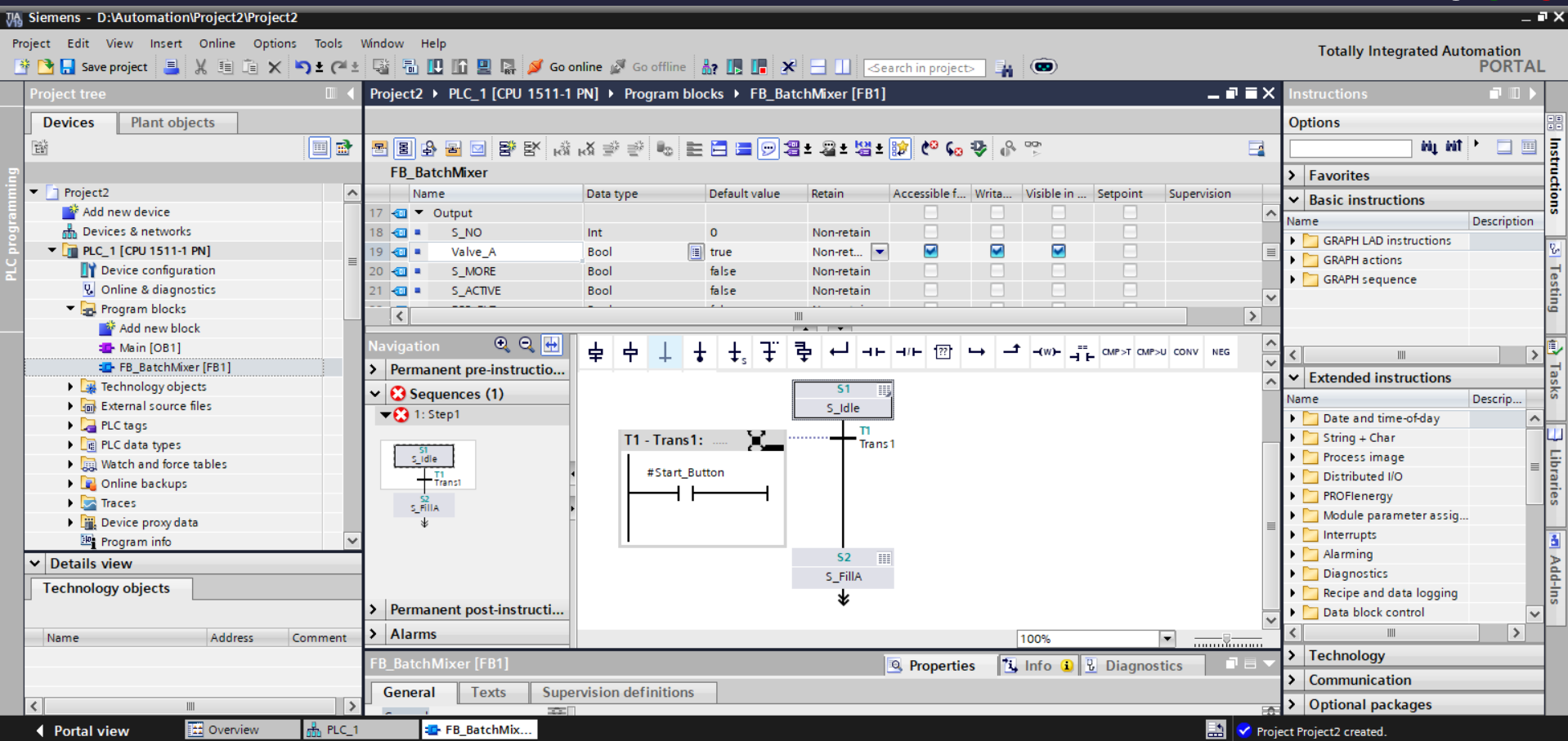
S_NO, Valve_A, S_MORE, S_ACTIVE. Navigation panel shows Sequences (1) with S_Idle active. Canvas shows T1-Trans1 with #Start_Button NO contact rung and S2 / S_FillA below.
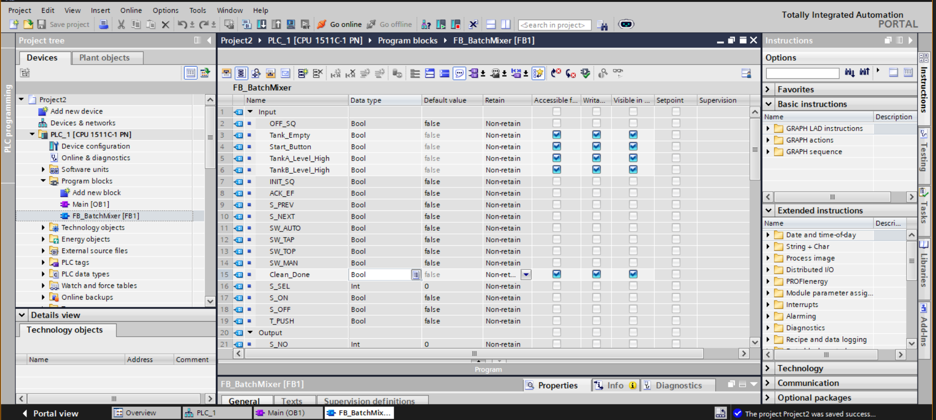
Start_Button, TankA_Level_High, TankB_Level_High, and Clean_Done. Mode selectors, acknowledgement flag (ACK_EF), and manual navigation inputs (S_PREV, S_NEXT) defined as internal-only.
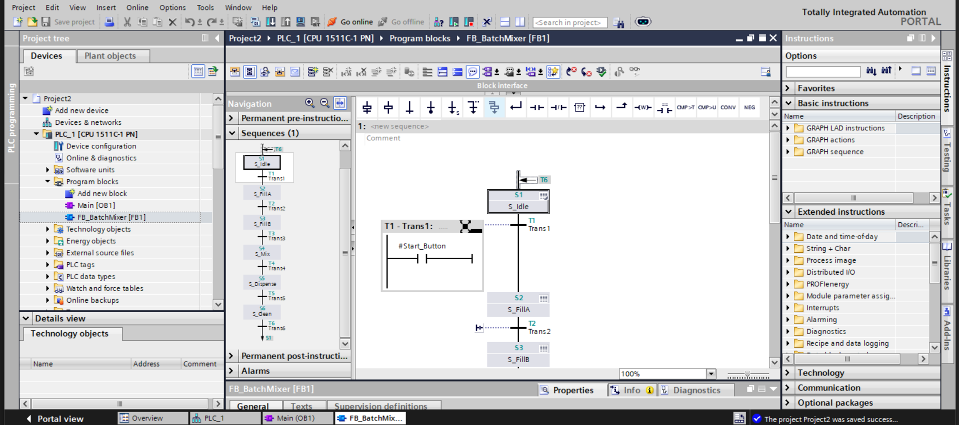
#Start_Button transition rung.
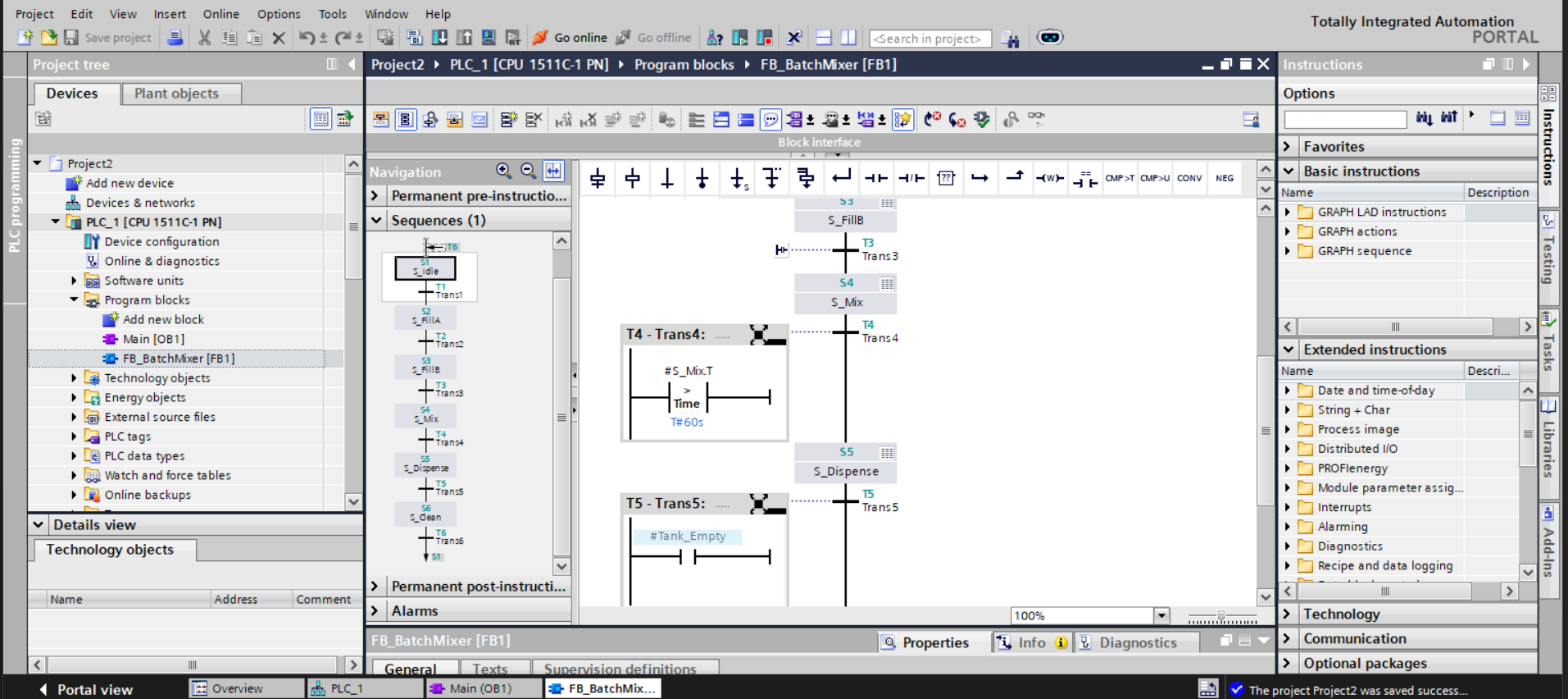
#S_Mix_T against T#60s. T5-Trans5 gates on #Tank_Empty. Steps S3 (S_FillB), S4 (S_Mix), and S5 (S_Dispense) visible in the sequence column.
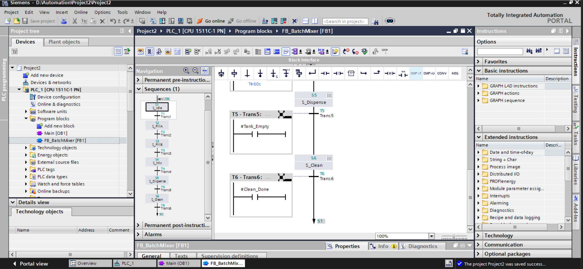
#Tank_Empty). T6-Trans6 evaluates #Clean_Done and the sequence pointer returns to S1 (arrow at canvas bottom), closing the cyclic batch loop.
Transition Logic — Annotated
# T1 - Trans1: S_Idle → S_FillA
# Condition: Start_Button asserted (NO contact, level-sensitive)
#Start_Button  |--[ ]--|--( )

# T2 - Trans2: S_FillA → S_FillB
# Sensor-gated: waits for actual level confirmation, not a fixed timer
# Prevents advancing early if supply pressure or inlet valve varies
#TankA_Level_High  |--[ ]--|--( )

# T3 - Trans3: S_FillB → S_Mix
# Same sensor-gated pattern as T2
#TankB_Level_High  |--[ ]--|--( )

# T4 - Trans4: S_Mix → S_Dispense
# S_Mix.T is GRAPH's native step elapsed timer
# Only accumulates while S_Mix is active; resets automatically on step exit
# No external TON instance required; no reset logic needed on cyclic re-entry
#S_Mix_T  |--CMP > --|--( )
           Time: T#60s

# T5 - Trans5: S_Dispense → S_Clean
# Drain completion gated on sensor state, not a timer
# Prevents S_Clean from starting before the tank has physically emptied
#Tank_Empty  |--[ ]--|--( )

# T6 - Trans6: S_Clean → S1 (cyclic reset)
# Clean_Done asserted externally by CIP controller or operator
# GRAPH routes sequence pointer back to S1 on satisfaction
# Batch cycle restarts without any external reset command
#Clean_Done  |--[ ]--|--( )  -->  S1
Engineering Decisions Worth Calling Out
- GRAPH over LAD for sequencing. A flat LAD implementation would require every stage to be evaluated in parallel every scan, with manual interlocks preventing overlap. GRAPH eliminates this — step activation is structurally enforced, and only the active step's actions execute each scan, reducing CPU load and making the control flow auditable at a glance.
-
Step-time over external TON for mixing.
#S_Mix.Tis scoped to the step itself — it cannot count while S_Mix is inactive, it resets on step exit, and it requires no wiring. An external TON would need itsINcoil gated through a step-active interlock and its output reset on each cyclic re-entry, adding three extra logic elements per timer for no functional benefit. - Sensor-gated fill transitions. Using level sensors for T2 and T3 rather than timed fills means the sequence is robust to supply pressure variation, inlet valve wear, and batch size changes. A timed fill would over- or under-fill the tank silently; a sensor-gated fill holds the step until the physical condition is confirmed.
-
N qualifier on all step outputs. Non-stored actions de-energise when the step becomes inactive. Without this, a valve opened in S_FillA would remain open through all subsequent steps until explicitly reset. Using
Nthroughout means each step owns exactly its outputs, and nothing more. -
SW_MAN / S_PREV / S_NEXT for commissioning. A technician can set
SW_MAN = TRUEand step through S_FillA → S_FillB → S_Mix individually, verifying each valve and sensor before running in auto. This is removed from the final HMI but remains in the FB interface for the automation engineer — no temporary LAD bypasses or debug blocks required. - S_NO output for HMI step tracking. Exposing the current step number as an Int output means the HMI can display contextual status ("Step 4 — Mixing") rather than just a generic "Running" indicator, giving operators actionable information without opening TIA Portal.
Testing & Debugging
The sequence was validated by stepping through each transition manually in SW_MAN mode, verifying that sensor inputs fired transitions correctly and that step outputs de-energised cleanly on exit. Key test cases:
- With
Start_Button = FALSE: sequence holds at S1 indefinitely — T1 correctly blocked - Asserting
Start_Button: sequence advances to S2 / S_FillA,Valve_Aenergises - Asserting
TankA_Level_High: T2 fires, S_FillA exits,Valve_Ade-energises (N qualifier confirmed working), S_FillB activates - Holding the mix step under 60 seconds: T4 correctly blocked, sequence holds in S_Mix
- Step timer exceeding 60 s: T4 fires, S_Mix exits, S_Dispense activates
- Asserting
Tank_Empty: T5 fires, S_Clean activates - Asserting
Clean_Done: T6 fires, sequence pointer returns to S1 — cyclic loop confirmed - Running two full cycles back-to-back: no state leakage between cycles, step timers reset correctly on re-entry
The Watch & Force table was used to monitor S_NO, S_ACTIVE, and the sensor inputs in real time during simulation, confirming that the diagnostic outputs tracked the sequence accurately at each stage.
Challenges Faced
The most significant conceptual challenge was adapting to GRAPH's execution model after working primarily in LAD. In LAD, every rung is evaluated every scan. In GRAPH, only the active step's actions execute — outputs in inactive steps are simply not evaluated. Initially this caused confusion when actuators appeared to behave inconsistently; the fix was understanding that GRAPH manages output scope through step activation, not through continuous coil evaluation.
The second challenge was the mixing timer. The first implementation used an external TON instance with its IN coil gated on S_ACTIVE. This worked on the first cycle but failed on the second — the TON's ET did not reset until IN went low, creating a one-scan window where T4 fired immediately on S_Mix re-entry before the timer had actually started. Replacing with #S_Mix.T eliminated the problem entirely since the step timer has no persistent state across step re-entries.
The third challenge was variable scoping. GRAPH strictly separates Inputs (readable in transitions) from Outputs (writable in step actions). A sensor signal incorrectly declared as an Output produced a compile error when used in a transition rung. Systematically reviewing the interface against GRAPH's variable access rules resolved this and produced a cleaner, more correctly structured block interface.
Development was also impacted by TIA Portal Cloud session timeouts. Unsaved GRAPH edits were lost on two occasions, requiring partial reconstruction of the sequence. This was mitigated by adopting a strict save-after-each-step discipline and capturing screenshots at every milestone.
Key Learning Outcomes
- Designing and implementing IEC 61131-3 Sequential Function Charts using Siemens GRAPH
- Step-transition sequencing with sensor-gated and time-gated transition conditions
- Step-action qualifier selection — Non-stored (
N), Set (S), Reset (R) - Using
S_StepName.T(step elapsed time) for duration control without external timers - Cyclic sequence design with automatic reset via terminal transition back to initial step
- Function Block interface design: correctly separating Inputs, Outputs, and internal flags
- HMI variable visibility configuration — Accessible / Writable / Visible flags on block interface variables
- Operating mode selector integration (
SW_AUTO,SW_MAN) for commissioning workflows - Exposing diagnostic outputs (
S_NO,S_ACTIVE) for operator HMI integration - Debugging sequential logic using Watch & Force tables and online diagnostics in TIA Portal
- Architectural separation of process logic (GRAPH FB) from organisational block (
OB1)
Tools & Technologies
- Siemens TIA Portal V18 (Cloud)
- S7-1511C-1 PN (CPU 1511C-1 PN)
- GRAPH programming language (IEC 61131-3 SFC)
- LAD (Ladder Diagram) for transition rung authoring within GRAPH
- Function Block (FB1) called from Organisation Block (OB1)
- PLC Tags & PLC Data Types editor
- Watch & Force tables for simulation and live monitoring
- Online diagnostics and step-monitoring view