Case Study: PLC Bridge Lighting Control System
A multi-state lighting controller implemented in OpenPLC Editor using IEC 61131-3 Ladder Diagram (LD)
Project Overview
This project implements a discrete, multi-state lighting controller using IEC 61131-3 Ladder Diagram logic. The system exposes three operational states — OFF, DIMMED, and FULL — driven by two momentary pushbutton inputs and enforced by interlocked rung logic. The exercise focuses on building deterministic state selection between mutually exclusive outputs, a foundational pattern in industrial mode-selection and lighting control routines.
Problem Statement
In industrial and operational environments, conflicting output commands can produce unsafe field conditions, contactor chatter, or damaged loads. A lighting controller offering multiple intensity levels must guarantee that no two driver outputs are energized simultaneously, regardless of operator input timing or button bouncing. The control strategy therefore requires a hardwired-style interlock implemented in software, ensuring deterministic selection between modes on every PLC scan cycle.
Solution
- PB_DIM → Normally Open (NO) momentary input requesting dimmed mode
- PB_FULL → Normally Open (NO) momentary input requesting full mode
- LIGHT_DIM → Discrete output coil driving the dimmed lighting circuit
- LIGHT_FULL → Discrete output coil driving the full-intensity lighting circuit
- Mutual Exclusion Interlock → Cross-wired NC feedback contacts preventing simultaneous energization of both outputs
Mutual exclusion was implemented by wiring a Normally Closed feedback contact of each output in series with the opposite rung's energizing path. When LIGHT_FULL is energized, its NC contact in the LIGHT_DIM rung is held open, blocking that rung from going true; the same relationship exists in the reverse direction. This software interlock mirrors the classical hardwired contactor-interlock pattern used in reversing starters and multi-mode drives, and ensures that any contention between the two pushbuttons resolves to a single active output on each scan cycle rather than driving both loads at once.
Project Screenshots


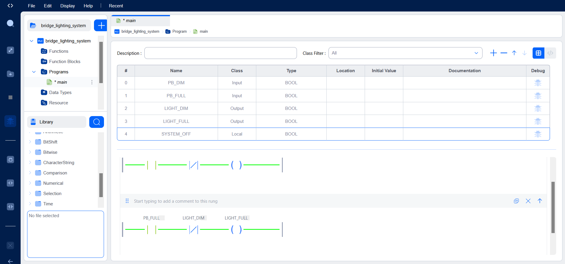
Variable Declarations
VAR_INPUT
    PB_DIM  : BOOL := FALSE;
    PB_FULL : BOOL := FALSE;
END_VAR

VAR_OUTPUT
    LIGHT_DIM  : BOOL := FALSE;
    LIGHT_FULL : BOOL := FALSE;
END_VAR
Testing & Verification
Functional verification was carried out using the OpenPLC runtime simulator and integrated debugger. Input variables were toggled and force-set during live execution to drive the system through each defined state and confirm that the interlock held under both sequential and simultaneous input conditions.
- Asserting
PB_DIMenergizesLIGHT_DIMwhile leavingLIGHT_FULLde-energized - Asserting
PB_FULLenergizesLIGHT_FULLand inhibitsLIGHT_DIMvia the cross-wired interlock - Simultaneous assertion of both inputs resolves to a single active output, never both — verifying the mutual exclusion holds at the rung level
- Releasing both inputs returns the system to the OFF state with both output coils de-energized
Challenges & Engineering Decisions
The principal challenge was reasoning through the mutual exclusion topology — specifically, deciding to use each output's own NC feedback contact as the inhibit signal on the opposing rung, rather than relying purely on input-side logic. Input-only interlocks would have left a narrow scan-cycle window where both outputs could briefly energize before the logic resolved; routing the interlock through the output feedback contacts ensures the inhibit is always in lockstep with the actual coil state.
This project deepened my understanding of state-based control and showed how compact Ladder Diagram structures can implement safety- and contention-critical behavior that would otherwise require either hardwired relay interlocks or more complex state-machine code in a text-based language.
Key Learning Outcomes
- Mutual exclusion and interlock design in Ladder Diagram
- Normally Open vs Normally Closed contact selection and its physical wiring analogue
- Coordinated control of multiple discrete outputs from a shared input set
- Introductory state-machine thinking applied within a cyclic scan execution model
- PLC runtime simulation, variable forcing, and edge-case verification
- Industrial mode-selection patterns transferable to lighting, HVAC, and motor-direction control
Tools & Environment
- OpenPLC Editor — IEC 61131-3 compliant programming environment
- Autonomy Edge — runtime/deployment platform
- Ladder Diagram (LD) — selected programming language for this routine
- OpenPLC Runtime Simulator and integrated debugger for live variable forcing