Case Study: PLC Start/Stop Motor Latching Circuit
An introductory PLC project implemented in OpenPLC Editor using IEC 61131-3 Ladder Diagram (LD)
Project Overview
This project implements a foundational industrial motor control routine using Ladder Diagram logic conforming to the IEC 61131-3 standard. The objective was to design and validate a Start/Stop control circuit incorporating a latching (seal-in) rung, ensuring the motor maintains an energized state after a momentary Start input and de-energizes deterministically upon a Stop input. The exercise emphasizes correct contact configuration, fail-safe wiring conventions, and verification through scan-cycle simulation.
Problem Statement
In production environments, a motor controller must not depend on the operator continuously holding a momentary push-button to maintain operation. Industry-standard control strategy requires that, once commanded ON, the motor remains energized through its own holding contact until an explicit Stop command — or a fault condition — breaks the circuit. The control logic must also adhere to fail-safe wiring principles, where a broken Stop circuit (e.g. a severed wire) results in the motor stopping rather than running uncontrolled.
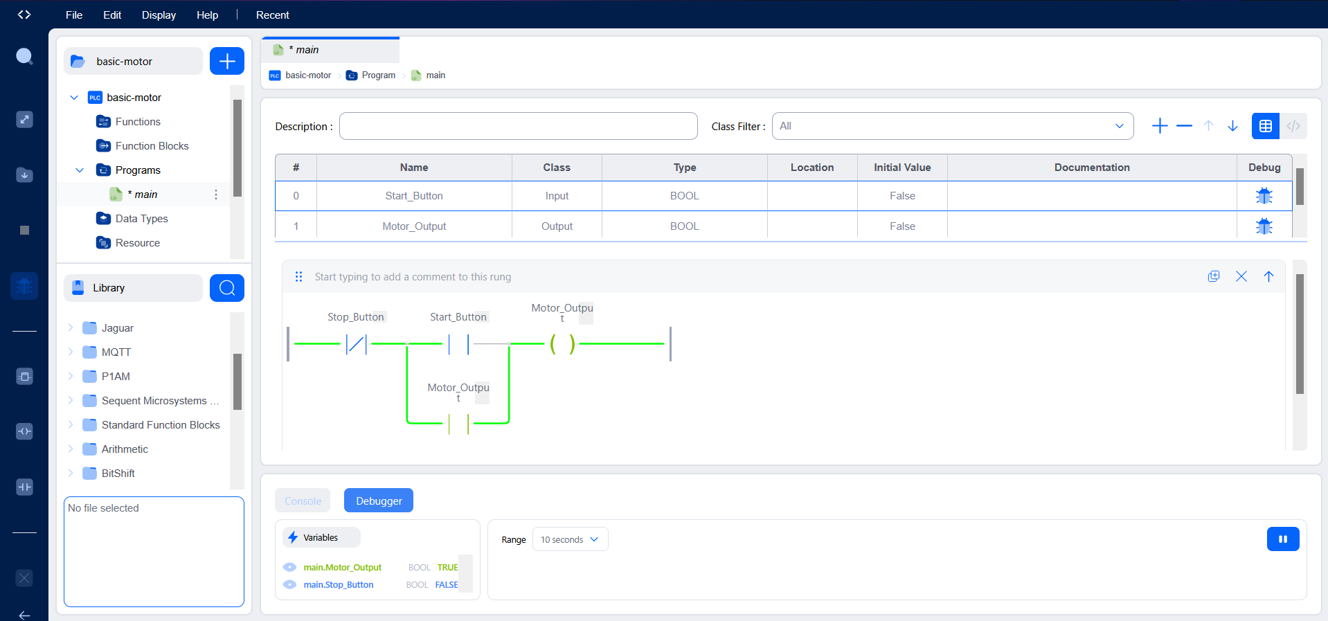
Solution
- Start_Button → Normally Open (NO) momentary contact, used as the energizing input
- Stop_Button → Normally Closed (NC) contact wired in series, ensuring fail-safe de-energization
- Motor_Output → Discrete output coil driving the motor contactor
- Seal-in Contact → Motor_Output feedback contact wired in parallel with Start_Button to maintain the latch
The seal-in branch implements a classical latching circuit: when Start_Button is briefly asserted, current flows through the rung, Motor_Output energizes, and its auxiliary contact closes in parallel with Start_Button. On the next scan cycle, even with Start_Button released, the latch path through the feedback contact keeps the rung true. The series-connected NC Stop_Button acts as the dominant de-energization path — opening it interrupts power flow through the rung, dropping the output and breaking the seal-in until Start is pressed again.
Project Screenshots
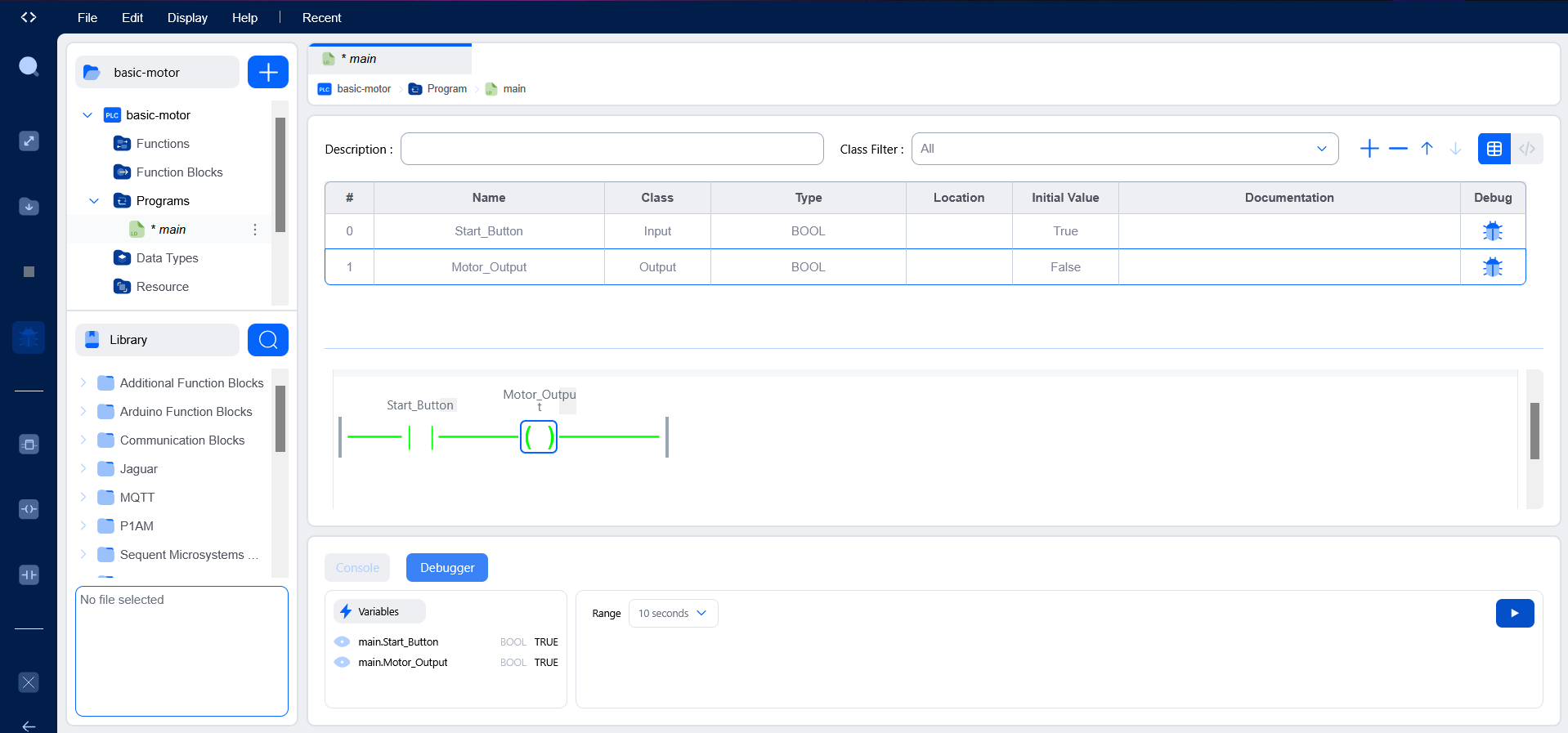
Variable Declarations
VAR_INPUT
    Start_Button : BOOL := FALSE;
    Stop_Button  : BOOL := TRUE;
END_VAR

VAR_OUTPUT
    Motor_Output : BOOL := FALSE;
END_VAR
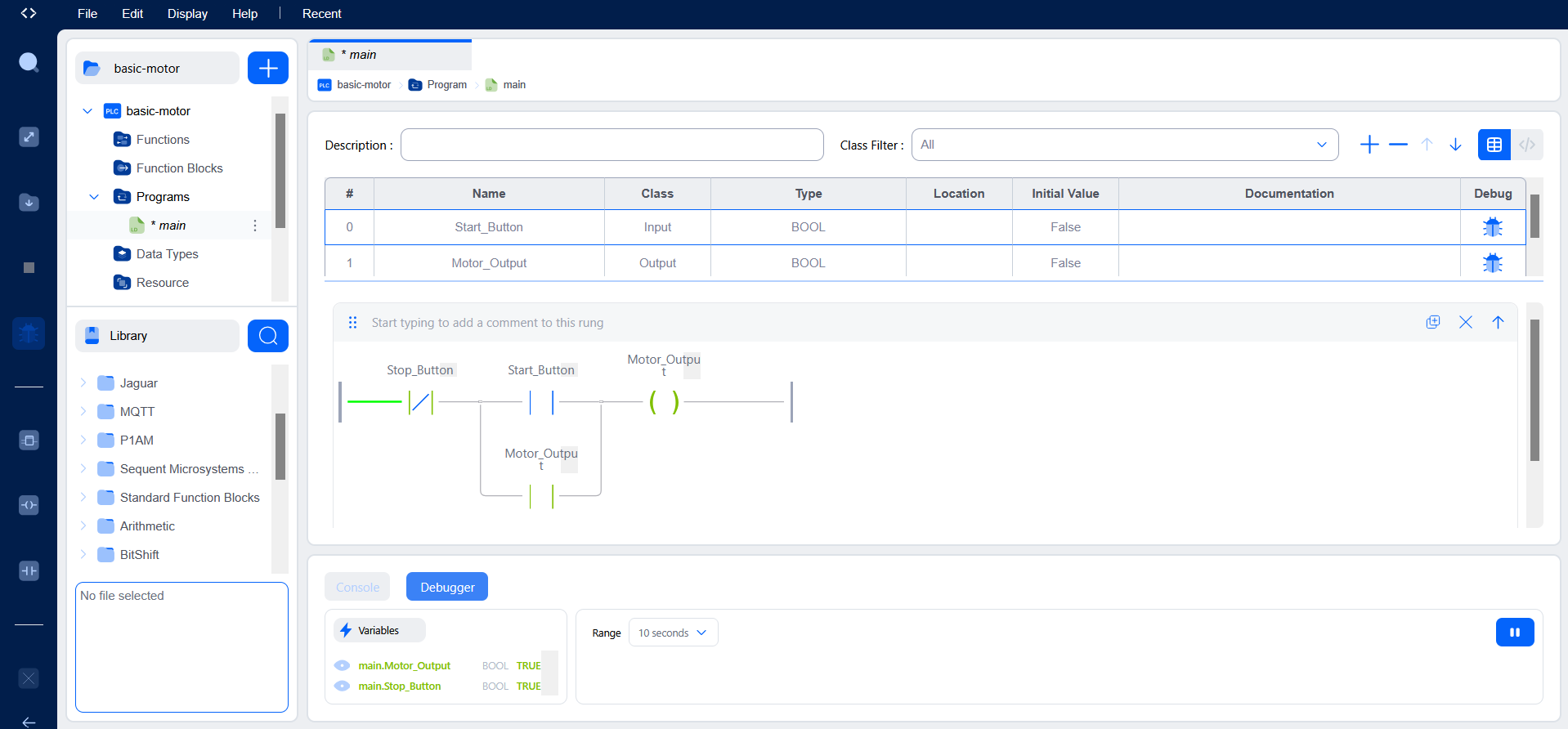
Testing & Verification
Functional verification was performed using the OpenPLC runtime simulator and integrated debugger. Boolean variables were force-set during live execution to drive the program through each defined state transition and confirm correct rung evaluation on every scan cycle.
- Asserting
Start_ButtonenergizesMotor_Outputwithin a single scan cycle - Releasing
Start_Buttonleaves the motor latched ON via the seal-in feedback contact - De-asserting
Stop_Buttonopens the series path, drops the output, and clears the latch - Re-asserting Stop_Button alone does not restart the motor — confirming correct latch behavior and operator intent
Challenges & Engineering Decisions
Early friction came from the OpenPLC Editor workflow itself —
particularly distinguishing between variable classes (VAR_INPUT,
VAR_OUTPUT, VAR_LOCAL) and configuring each I/O point with the correct
data type and initial value. Selecting an initial value of TRUE for
Stop_Button required deliberate reasoning: because the physical
push-button is wired Normally Closed, its idle (un-pressed) state is
logically TRUE, and this initialization mirrors real-world fail-safe
wiring inside the simulation environment.
Working in a graphical IEC 61131-3 environment also reframed how I approach control flow compared to text-based software engineering. In Ladder Diagram, execution is governed by the cyclic scan model rather than sequential statements — every rung is re-evaluated each cycle against the current input image, so logic must be designed with that deterministic, repeating execution in mind.
Key Learning Outcomes
- IEC 61131-3 Ladder Diagram fundamentals and rung-based logic design
- Distinction between Normally Open and Normally Closed contacts and their physical wiring implications
- Output coil energization and seal-in (latching) circuit construction
- PLC scan cycle behavior and deterministic rung evaluation
- Runtime simulation, variable forcing, and systematic debugging methodology
- Fail-safe control design principles applied to industrial motor starters
Tools & Environment
- OpenPLC Editor — IEC 61131-3 compliant programming environment
- Autonomy Edge — runtime/deployment platform
- Ladder Diagram (LD) — selected programming language for this routine
- OpenPLC Runtime Simulator and integrated debugger for live variable forcing